Pluggable module having ejector device

a technology of ejector device and pluggable module, which is applied in the direction of coupling device connection, optical element, instruments, etc., can solve the problems of high manufacturing cost and inconvenient manual push of ejector block at that location, and achieve the effect of easy release of the pluggable modul

Inactive Publication Date: 2010-11-30
HON HAI PRECISION IND CO LTD
View PDF8 Cites 28 Cited by
  • Summary
  • Abstract
  • Description
  • Claims
  • Application Information

AI Technical Summary

Benefits of technology

[0007]Object of the present invention is to provide a pluggable module having an improved ejector device for easily releasing the pluggable module from a mating receptacle cage.
[0008]The present invention provides a pluggable module retained in a mating receptacle cage which has a retaining tab. The pluggable module comprises a housing, an ejector device and a printed circuit board mounted into the housing. The housing comprises a latch portion retained in the retaining tab, a recessing portion defined on a surface thereof, at least one inclined portion located on the surface of the recessing portion and adjacent to the latch portion. The ejector device comprises a spring member slidably received in the recessing portion and a driving portion for pulling the spring member forwardly. When the pluggable module being ejected from the receptacle cage, the spring member is guided by the inclined portion of the housing and upwardly resists against the retaining tab for releasing the latch portion of the housing from the retaining tab of the receptacle cage in order to easily withdraw the pluggable module from a mating receptacle cage. The construction of the ejector device is so simple that the cost of the manufacture has been saved.

Problems solved by technology

However, it is complicated to assembly the de-latch mechanism to the housing of the transceiver and resulted in a high cost of the manufacture.
However, it is inconvenient to manually push the ejecting block at that location.
This is particularly so in modern systems having high port densities in and around the cage that restrict access to the ejecting block.

Method used


Image

  • Pluggable module having ejector device
  • Pluggable module having ejector device
  • Pluggable module having ejector device

Examples


Embodiment Construction

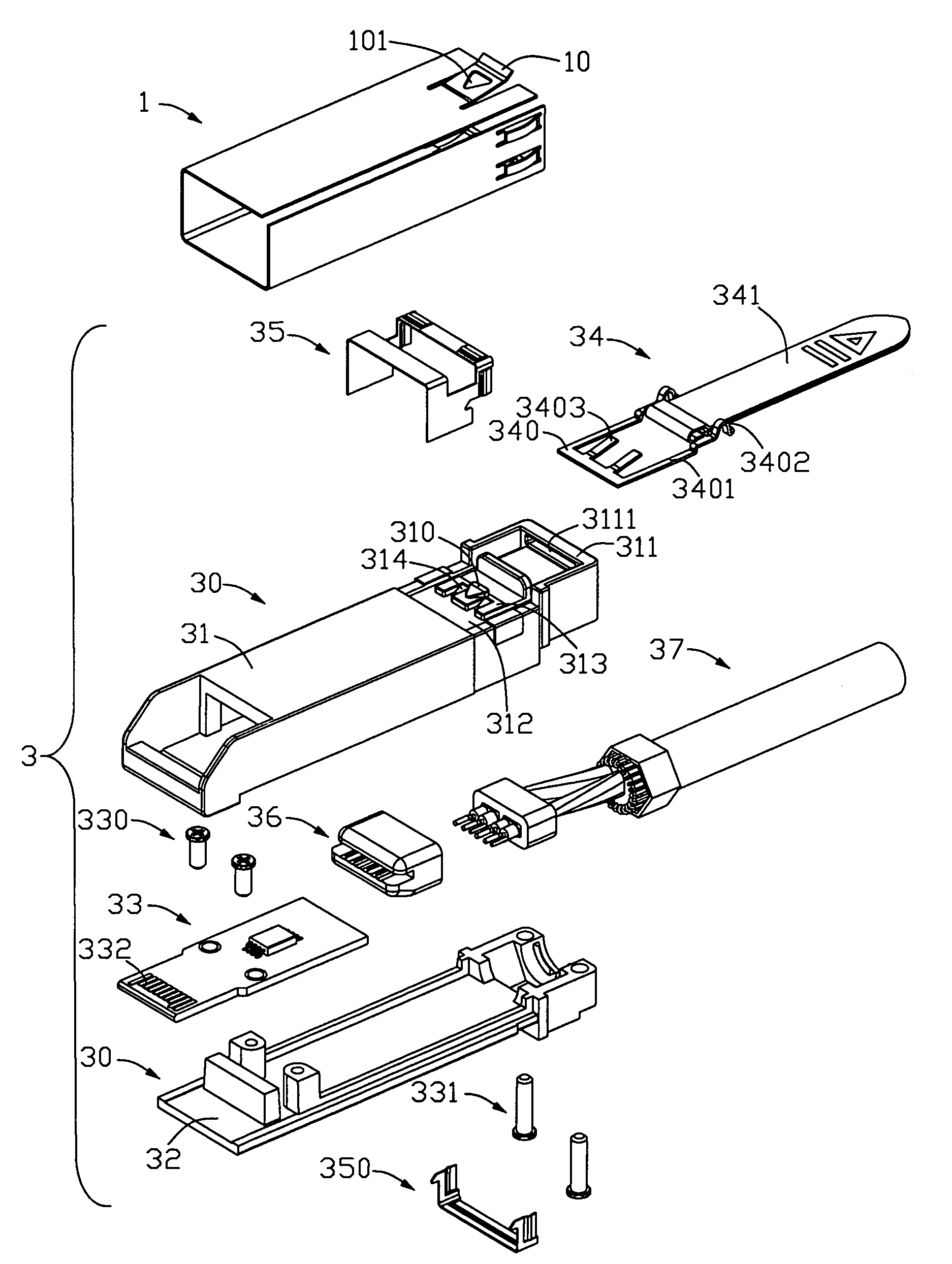
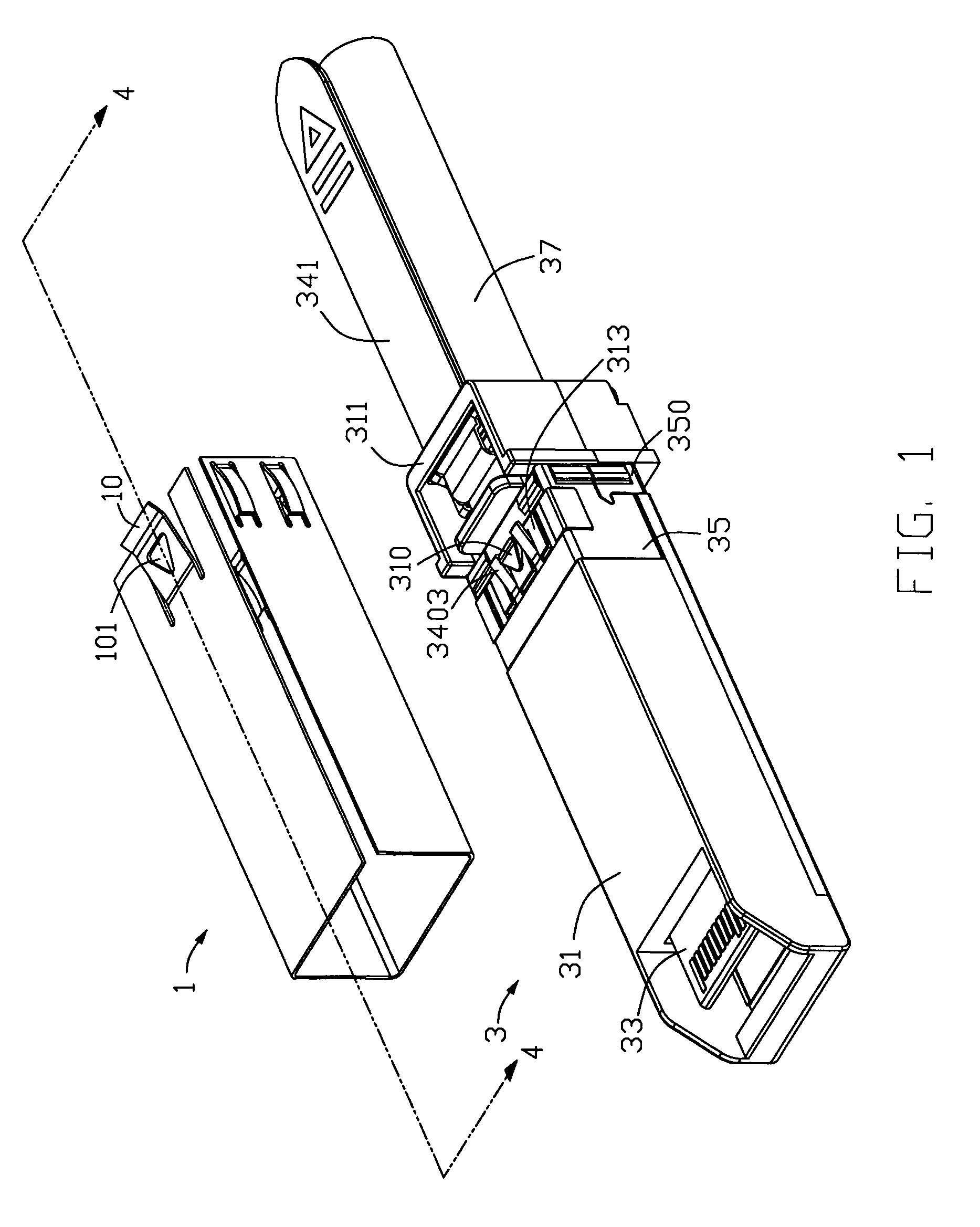
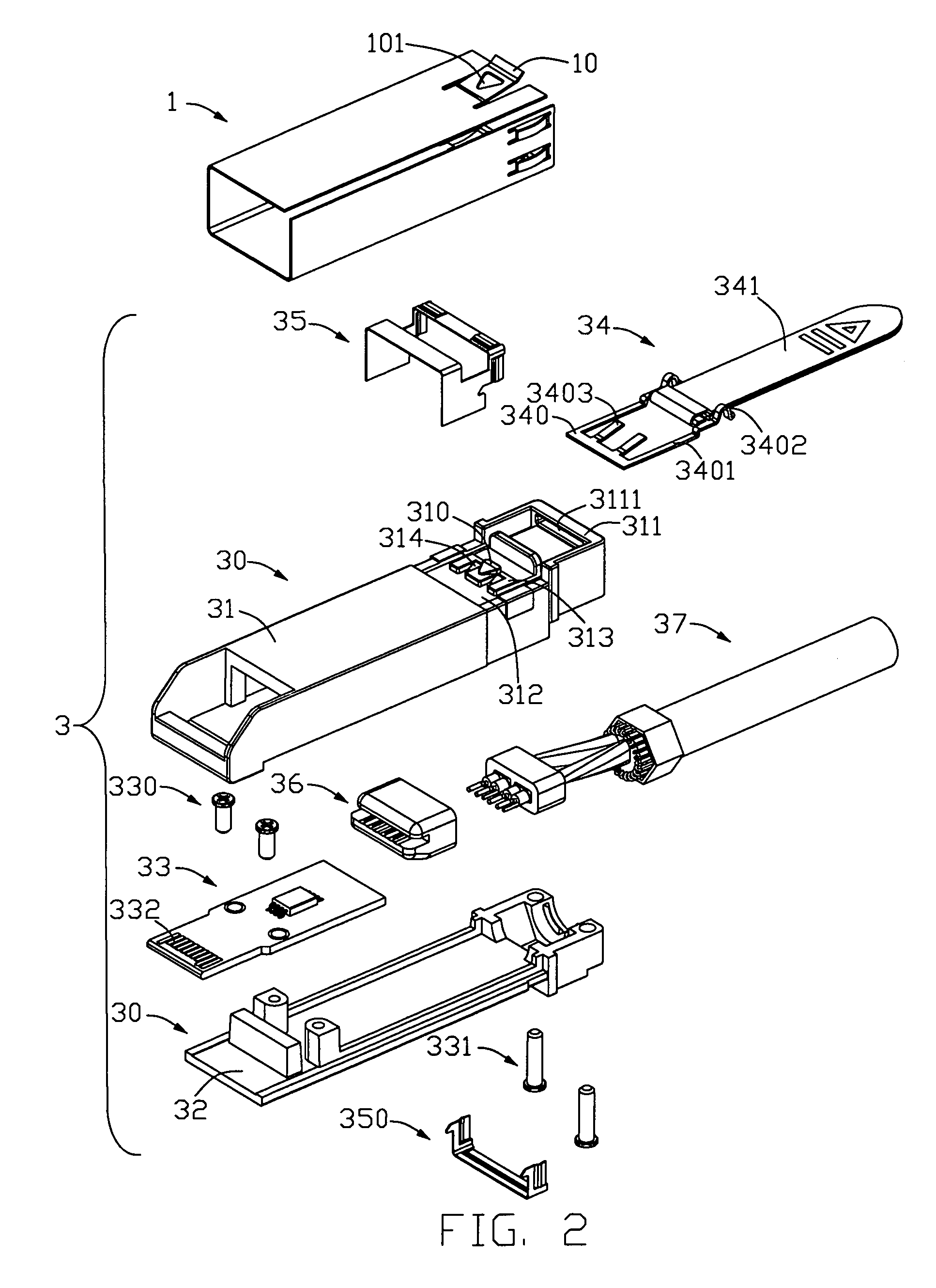
[0016]Reference will now be made to the drawing figures to describe the present invention in detail. Referring to FIGS. 1 and 2, a pluggable module 3 retained in a receptacle cage 1 has a housing 30, an ejector section 34 and a printed circuit board 33 mounted into the housing 30. The receptacle cage 1 comprises a retaining tab 10 having an aperture 101 defined thereon.

[0017]Referring to FIGS. 1-3, the housing 30 includes a top housing 31 and a bottom housing 32. The top housing 31 has a recessing portion 312 defined on a surface thereof, an E-shaped step 313 disposed on a surface of the recessing portion 312, a latch portion 310 formed on the E-shaped step 313 and retained in the aperture 101 of the retaining tab 10, a pair of inclined portions 314 respectively located adjacent to the latch portion 310. The top housing 31 further comprises a blocking wall 311 disposed thereon.

[0018]Referring to FIGS. 2-6, the ejector device 34 comprises a spring member 340 slidably received in the ...


PUM


Abstract

A pluggable module (3) retained in a mating receptacle cage (1) which has a retaining tab (10) includes a housing (30) and an ejector device (34). The housing has a latch portion (310) retained in the retaining tab, a recessing portion (312) defined on a surface thereof, at least one inclined portion (314) located on the surface of the recessing portion. The ejector device includes a spring member (340) slidably received in the recessing portion and a driving portion (341) for pulling the spring member forwardly. The spring member is guided by the inclined portion and upwardly resists against the retaining tab for releasing the latch portion of the housing from the retaining tab of the receptacle cage.

Description

BACKGROUND OF THE INVENTION[0001]1. Field of the Invention[0002]The present invention relates to a pluggable module, and particularly to pluggable module having ejector device which is used to withdraw the pluggable module from a mating receptacle cage.[0003]2. Description of the Prior Art[0004]A small form-factor pluggable transceiver (SFP transceiver) provides a link between an electronic transmission line and an optical transmission line as a bi-direction optoelectronic converter. U.S. Pat. No. 6,744,963 issued to Jenq-Yih Hwang on Jun. 1, 2004 discloses an EMI-minimized transceiver received in a transceiver cage. The transceiver includes a housing having a latch, an ejector mounted to a passage defined in the housing for disengaging the latch from a retaining tab of the cage, and a de-latching mechanism having a driving device and a linking rod. The driving device is rotatably attached to the upper portion of the housing and movably engaged with the ejector. Pulling the driving ...

Claims


Application Information

Patent Timeline
Patent Type & Authority Patents(United States)
IPC IPC(8): H01R13/627
CPCG02B6/4246H01R13/508H01R13/6583G02B6/4292H01R13/6658G02B6/4284
Inventor ZHANG, XUE-LIANGZHU, QING-MANWANG, CHIEN-CHIUNG
Owner HON HAI PRECISION IND CO LTD
Why Eureka
Try Eureka