Shift-by-wire control system for automatic transmission device and method for the same

a technology of automatic transmission device and control system, which is applied in the direction of mechanical control device, anti-theft device, instruments, etc., can solve the problems of vehicle theft and vehicle th

Active Publication Date: 2010-12-07
DENSO CORP +1
View PDF21 Cites 22 Cited by
  • Summary
  • Abstract
  • Description
  • Claims
  • Application Information

AI Technical Summary

Problems solved by technology

Accordingly, the vehicle may be stolen, even when the vehicle is parked in a condition where the automatic transmission device is set at the P-range and is in the lock state.
In this case, the vehicle may be stolen.

Method used


Image

  • Shift-by-wire control system for automatic transmission device and method for the same
  • Shift-by-wire control system for automatic transmission device and method for the same
  • Shift-by-wire control system for automatic transmission device and method for the same

Examples


Embodiment Construction

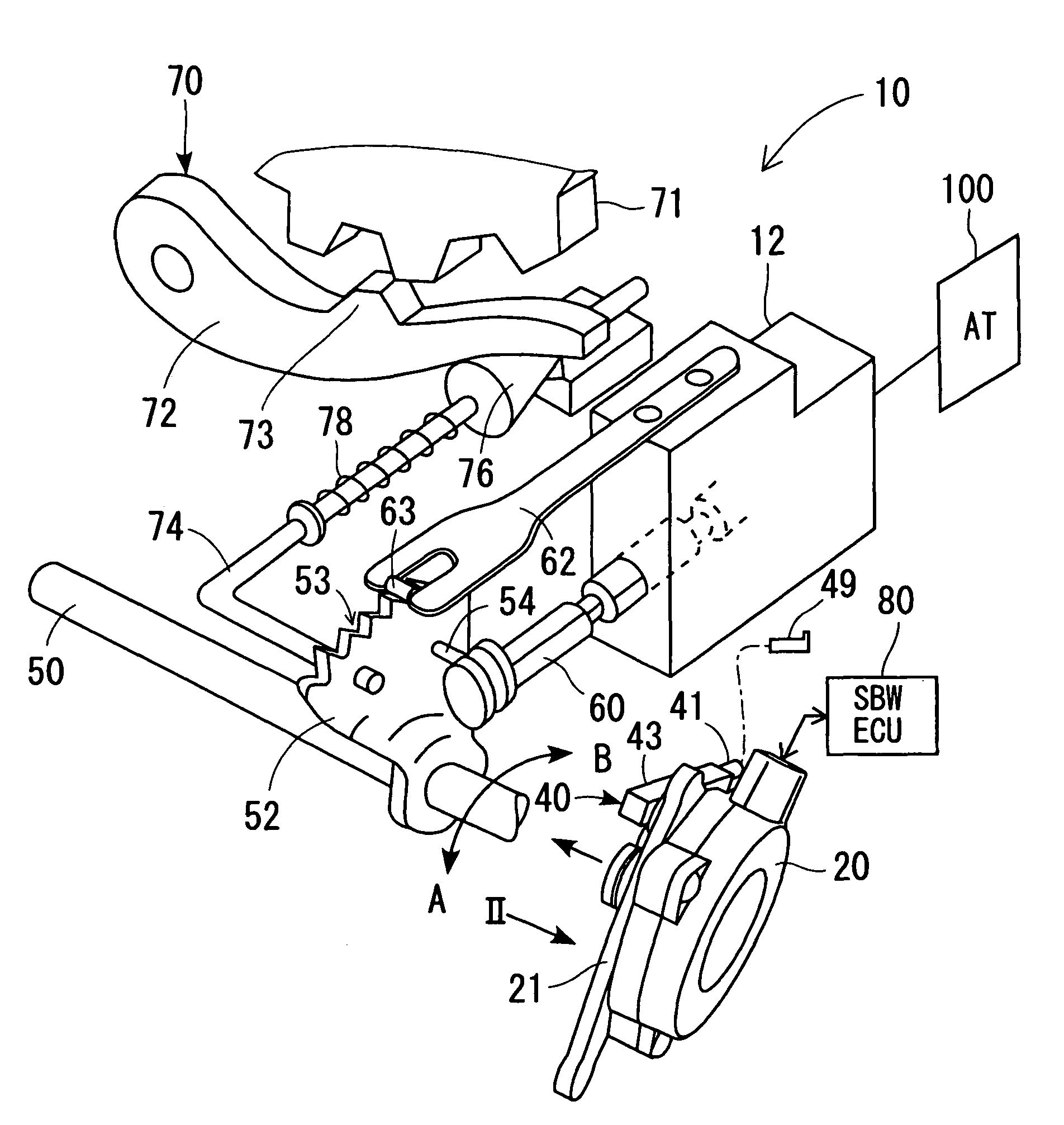
[0013]First, a shift-by-wire control system 10 is described with reference to FIG. 1. The shift-by-wire control system 10 is provided for controlling a vehicle such as a two-wheel drive vehicle and a four-wheel drive vehicle. The shift-by-wire control system 10 includes an actuator 20, an ECU 80, a parking lock device 70, and an automatic transmission control device 12. The ECU 80 is provided for controlling the shift-by-wire control system (SBW system) 10.

[0014]The ECU 80 is an electronic circuit constructed of a microcomputer having a CPU, a RAM, a ROM, an EEPROM, and the like, for controlling the shift-by-wire control system 10. A driver operates, for example, an unillustrated shift lever to select an instruction shift range. The ECU 80 detects the instruction shift range, thereby manipulating the actuator 20 corresponding to the instruction shift range, so that the ECU 80 controls an axial position of a manual valve 60 serving as a range switching unit.

[0015]The manual valve 60 ...


PUM


Abstract

A shift-by-wire control system includes a parking lock device that brings an output shaft of an automatic transmission device to a lock state when a range switching unit switches to the P-range. The parking lock device brings the output shaft to a lock-release state when the range switching unit switches to another shift range. An electric motor actuates the range switching unit and the parking lock device in accordance with an instruction of an operator. A manual device transmits manual operation force of the operator to the parking lock device when the electric motor stops. The manual device includes a one-way transmission unit permitting transmission of the manual operation force in a direction toward the lock state, and prohibiting transmission of the manual operation force in a direction toward the lock-release state.

Description

CROSS REFERENCE TO RELATED APPLICATIONS[0001]This application is based on and incorporates herein by reference Japanese Patent Application No. 2006-215392 filed on Aug. 8, 2006.FIELD OF THE INVENTION[0002]The present invention relates to a shift-by-wire control system for an automatic transmission device. The present invention further relates to a method for operating the shift-by-wire control system.BACKGROUND OF THE INVENTION[0003]U.S. Pat. No. 6,752,036 B2 (JP-A-2004-513307) discloses a shift-by-wire control system including an electric motor for actuating a range switching unit. Specifically, the shift-by-wire control system detects an instruction shift range selected by an occupant of a vehicle, so that the electric motor actuates the range switching unit to switch a shift range of the vehicle in accordance with the instruction shift range. In a conventional shift-by-wire control system, a parking lock device brings an output shaft of an automatic transmission device to a lock ...

Claims


Application Information

Patent Timeline
Patent Type & Authority Patents(United States)
IPC IPC(8): F16H59/00B60K20/00B60K17/04B60W10/10F16H61/28F16H63/34
CPCF16H61/32F16H63/3458F16H2061/326Y10T477/649Y10T74/2003Y10T74/20085Y10T74/19251F16H63/34F16H63/00B60R25/06F16H63/30
Inventor YOSHIYAMA, SHIGERUKIMURA, KIYOSHIITOH, TAKUOISHI, KENICHIKAMADA, ATSUSHINOZAKI, YOSHINOBU
Owner DENSO CORP
Why Eureka
Try Eureka