Emergency lighting system

a technology of emergency lighting and emergency lighting, applied in emergency power supply arrangements, active radio relay systems, wireless communication, etc., can solve the problems of bulky wiring and difficult installation in old buildings

Active Publication Date: 2010-12-07
THOMAS & BETTS INT INC
View PDF28 Cites 50 Cited by
  • Summary
  • Abstract
  • Description
  • Claims
  • Application Information

AI Technical Summary

Benefits of technology

[0008]transmitters and receivers for producing a mesh network for providing wireless communication of data between the controller and the emergency devices so that the operability of the plurality of emergency devices in an emergency situation can be tested by a wireless signal over the mesh network to the emergency devices to initiate a test operation of the devices and for communicating data relating to the test back to a control receiver;
[0024]This aspect of the invention enables different groups of devices to be tested at different times. It is not desirable to test all devices in the one physical area at the same time because at the conclusion of the test, the devices may need to recharge their power supply, such as batteries, and are thus unable to operate in the event of a genuine emergency. Thus, if the devices are allocated to groups, dispersed devices can be tested in a group whilst other devices in close proximity are not tested. Thus, if there is a genuine emergency situation, whilst the tested group are recharging, the devices in other groups are able to operate in the emergency situation and because of their close proximity to the tested device, the failure of the tested device to operate is less likely to create a difficulty. That is, if the devices are emergency exit lights, other devices in the proximity will show the way to the exit and the fact that one device may not operate should not impair operation of the entire system to show an emergency exit path from an environment. On subsequent days, other groups of devices can be tested after sufficient time has elapsed for the previously tested devices to recharge or otherwise recover from the test operation.

Problems solved by technology

Such wiring is bulky and not easy to install in old buildings.

Method used


Image

  • Emergency lighting system
  • Emergency lighting system
  • Emergency lighting system

Examples


Embodiment Construction

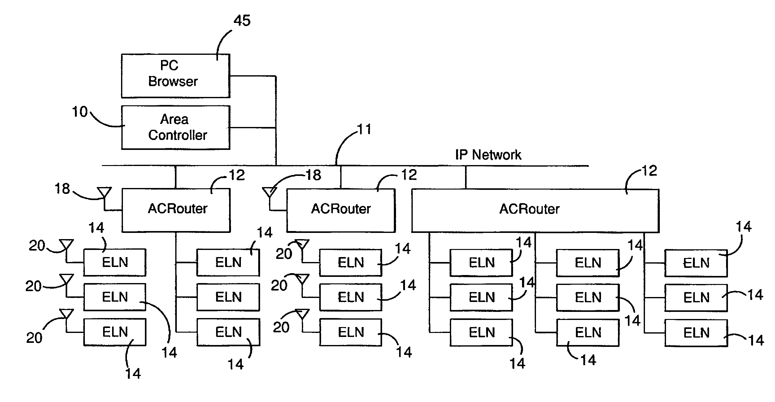
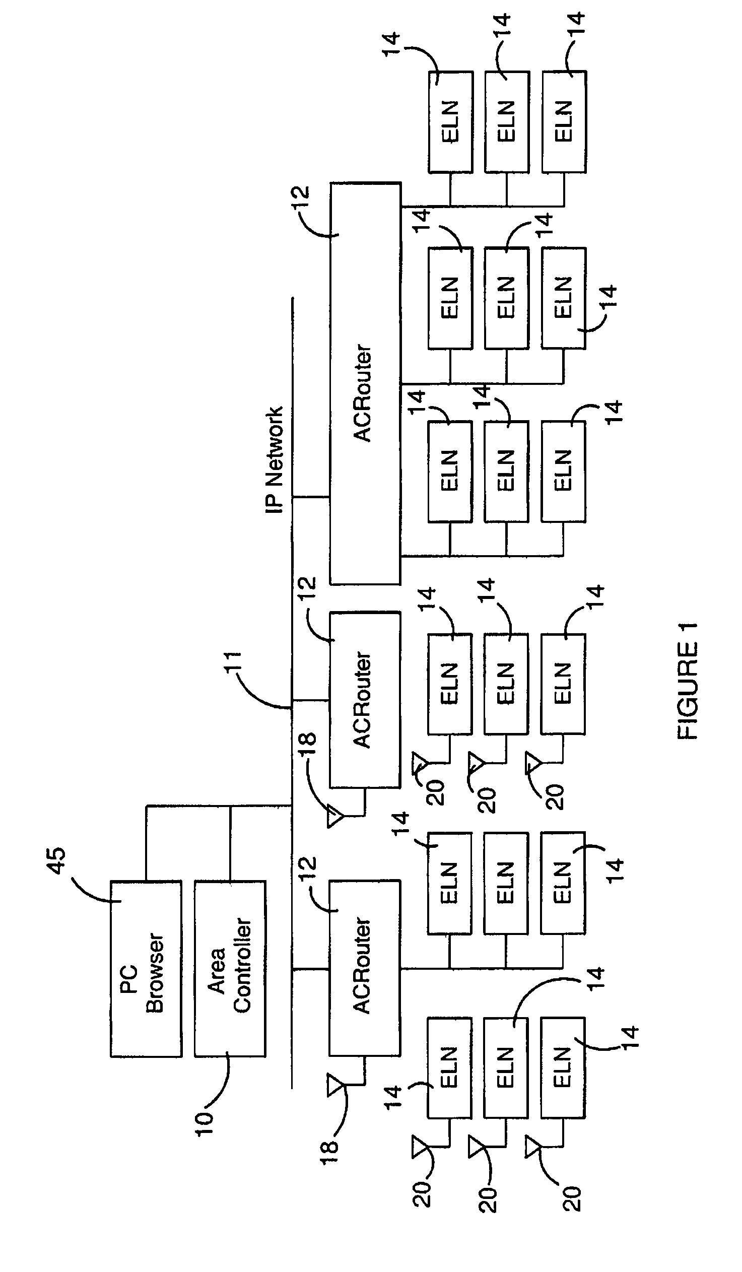
[0059]With reference to FIG. 1, an emergency system such as an emergency lighting system is shown which comprises a central area controller 10 which is connected to a number of routers 12 via a network 11 which may comprise the internet, a LAN, a WAN, or a PSTN. Other communication networks could also be used.

[0060]Each router communicates with a plurality of devices 14. If the system is an emergency lighting system, the devices 14 are emergency lighting devices which are illuminated or remain illuminated in an emergency situation when power is cut off to an area so that the lighting devices 14 are visible and can show an exit path or an exit direction, etc. from a building. Most typically, the devices are exit signs. Other emergency devices include Spitfires (non-maintained quartz halogen incandescent ceiling mounted light fittings), fluorescent battens and Floods (non-maintained twin directional incandescent wall mounted light fittings).

[0061]In the embodiments shown, some of the ...


PUM


Abstract

An emergency system for providing an emergency function is described in which the system is required to provide an autonomous and self-diagnostic capability so the system can be tested when not in operation in an emergency situation. A plurality of emergency devices 14 are provided which have transmitters and receivers for producing a mesh network (FIG. 1). Each device 14 has a processor 60 for establishing a preferred wireless communication link of the mesh network to another device 14 for relaying signals and messages. The devices 14 are arranged in subnets 50 and the subnets are also grouped into groups of devices 14 which may cross various subnets 50 so that only one group of devices 14 can be tested at a particular time.

Description

CROSS-REFERENCE TO RELATED APPLICATION[0001]This application claims priority to Australian Application No. AU 2006904063, filed Jul. 26, 2006, the contents of which are incorporated herein by reference.FIELD OF THE INVENTION[0002]This invention relates to an emergency system for providing an emergency function and an emergency device for use in such a system. The invention has particular application, but not exclusive application, to emergency lighting systems.BACKGROUND OF THE INVENTION[0003]Emergency devices such as emergency lighting for use in buildings and the like are each provided with an autonomous and self-diagnostic capability so that the light can be tested to ensure that it will operate in an emergency situation in the event of loss of power to a building. Typically, tests take place on a routine basis such as a monthly and annual basis. In Australia, standards prescribe tests on a six monthly basis. Data is sent back to a central server for analysis and display so that ...

Claims


Application Information

Patent Timeline
Patent Type & Authority Patents(United States)
IPC IPC(8): H04B7/15H04W84/18
CPCH02J9/02H04W84/18H05B37/034H05B47/22
Inventor HO, DANG HAILAVRENCIC, DRAGOFINCH, MICHAEL DOUGLASKOCSI, ZOLTAN
Owner THOMAS & BETTS INT INC
Why Eureka
Try Eureka