
Traffic shaping method and device

a traffic shaping and traffic technology, applied in data switching networks, frequency-division multiplexes, instruments, etc., can solve problems such as packet discarding, problem to occur, increase in appliance cost, etc., and achieve the effect of reducing discard/latency and reducing discard/latency

Inactive Publication Date: 2010-12-21
ALAXALA NETWORKS
View PDF16 Cites 7 Cited by
  • Summary
  • Abstract
  • Description
  • Claims
  • Application Information

AI Technical Summary

Benefits of technology

The solution effectively reduces latency and packet discard for real-time traffic while ensuring fair frame rate distribution, optimizing network resource usage and maintaining communication quality by prioritizing high-priority traffic and managing frame rates to prevent buffer shortages.

Problems solved by technology

Accordingly, there is a danger of causing a problem to occur, such as connectivity due to the appliance.
Consequently, there is a danger of resulting in a packet discard due to the buffer shortage, or an increase in the appliance cost.
The traffic burst, however, cannot be suppressed on each session (i.e., queue) basis.
Consequently, there is a danger of causing a problem that traffic's latency fluctuation (i.e., latency jitter), which occurs by the traffic's having been transmitted via the network, will be propagated as it is.
Consequently, there is a possibility of resulting in a lowering in the communications quality.
In the case of this configuration, however, it is difficult to guarantee sufficient latency quality with respect to the real-time traffics.
As a result, the transmission timing for the high-priority traffic is delayed because of the competition of the scheduling processing with the low-priority traffic of another user.
As the users which perform the scheduling increase in number, it becomes more and more difficult to neglect the latency due to the inter-users scheduling.
Accordingly, it is difficult to offer the sufficient latency quality to the real-time traffics.
Accordingly, it is difficult to reduce the latency with respect to the real-time traffics.
Consequently, there is a problem that the traffic shaping on each service-point basis, i.e., the present requirement, will exhibit no effect.

Method used


Image

  • Traffic shaping method and device
  • Traffic shaping method and device
  • Traffic shaping method and device

Examples


Embodiment Construction

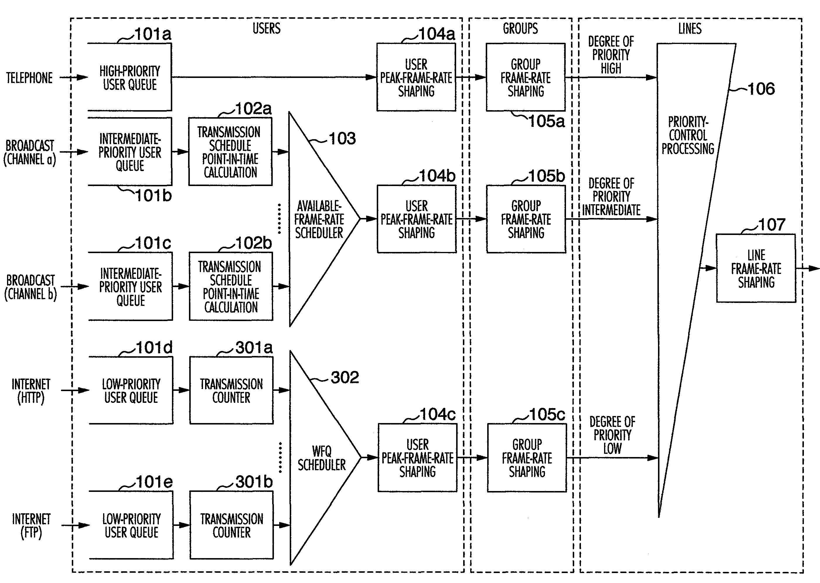
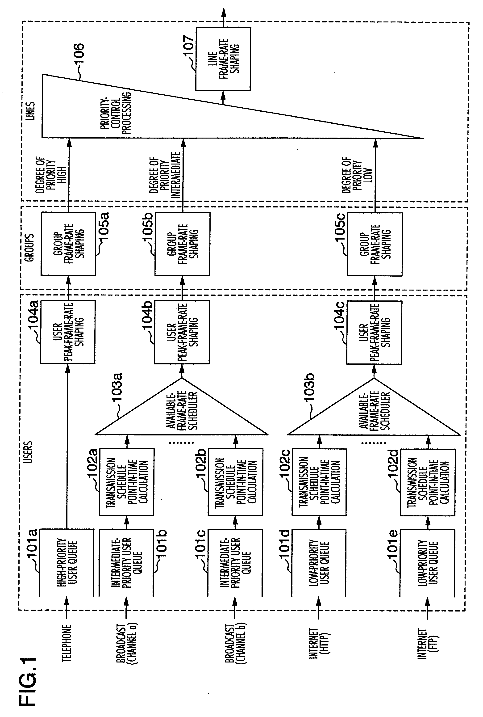
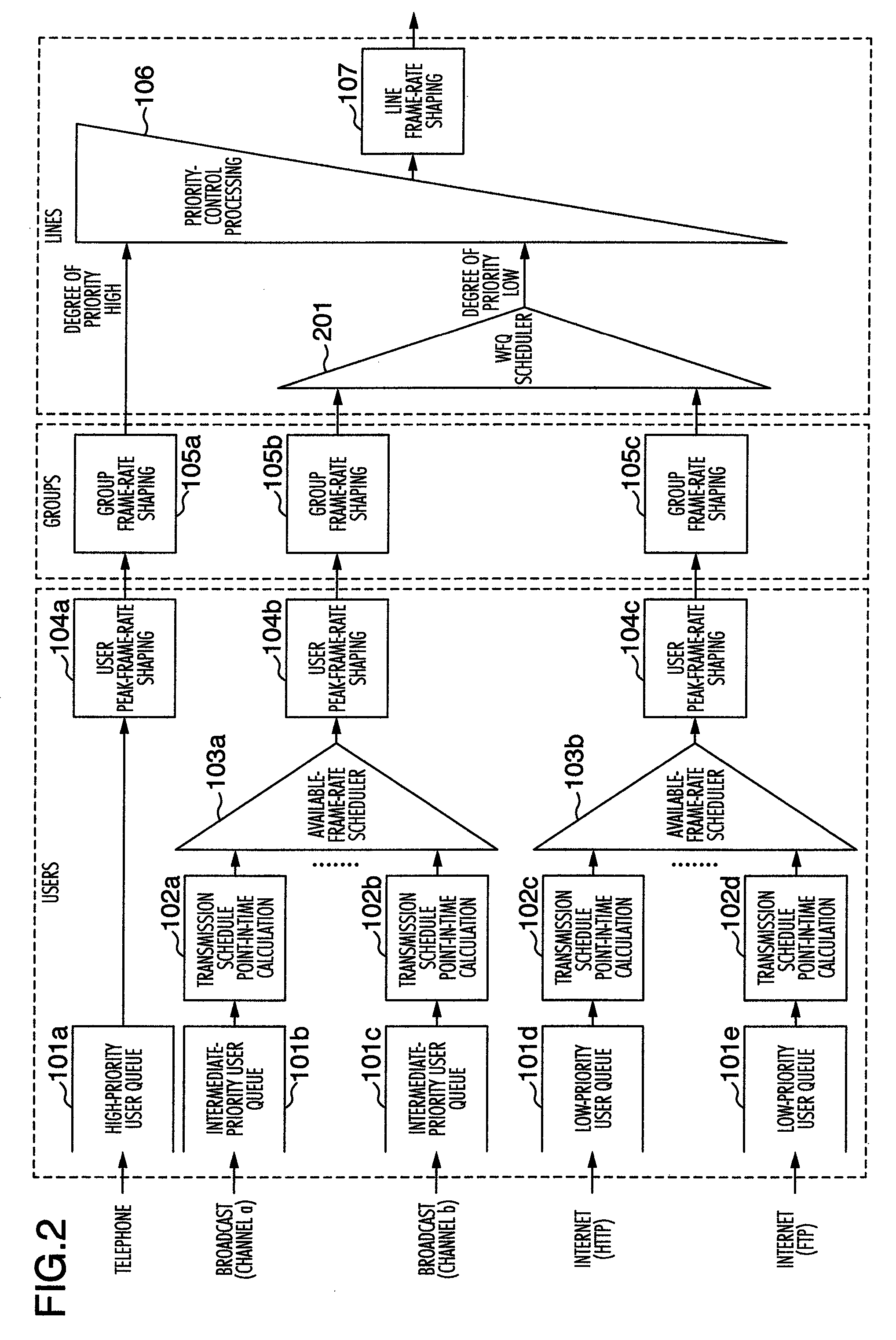
[0028]In order to implement the network requirement (1), in a traffic shaping device in the present embodiment, as illustrated in FIG. 1, there is provided a mechanism including the following configuration components: High-priority / intermediate-priority / low-priority user queues 101 for performing queuing of traffics by classifying the traffics into, e.g., the high-priority / intermediate-priority / low-priority for each service of the telephone / broadcast / Internet, transmission schedule point-in-time calculations 102 having a function for calculating available frame rate from peak-frame-rate / minimum-frame-rate / weight set for each user, and managing a transmission schedule point-in-time determined from the peak-frame-rate / available-frame-rate, available-frame-rate schedulers 103 for controlling a scheduling in accordance with the transmission schedule point-in-time of the available frame rate transmitted from the transmission schedule point-in-time calculations 102, user peak-frame-rate s...


PUM


Abstract

A packet relay device comprises a distribution processing unit classifying traffics into groups and users based on header information of packets received; a calculation unit calculating available frame rate of each user from peak frame rate, minimum frame rate, and weight information set for each user; a scheduling control unit updating a transmission schedule point-in-time calculated based on the available frame rate of each user, and judging which packet should be transmitted in accordance with the transmission schedule point-in-time updated; and a shaping unit updating a transmission schedule point-in-time calculated based on the peak frame rate of each user, and performing a shaping of packets at the peak frame rate on each user basis in accordance with the transmission schedule point-in-time updated; and a priority-control processing unit performing a strict priority control over transmission of packets of each group in correspondence with degree of priority of each group.

Description

INCORPORATION BY REFERENCE[0001]The present application claims priority from Japanese application JP2008-018490 filed on Jan. 30, 2008, the content of which is hereby incorporated by reference into this application.BACKGROUND OF THE INVENTION[0002]1. Field of the Invention[0003]The present invention relates to a traffic shaping method and device in communications fields.[0004]2. Description of the Related Art[0005]In recent years, significant progress has been made in implementation of the broadband in IP networks. In accompaniment with this progress, there has been a more and more growing trend to implement high-real-time-property contents such as telephones and broadcasts on the IP networks in addition to Internet traffics such as HTTP and FTP. Properties of the traffics like these and traffic control requirements needed for network environments range over a variety of types. Accordingly, in order to address these various types of requests, availability-having traffic control tech...

Claims


Application Information

Patent Timeline
Patent Type & Authority Patents(United States)
IPC IPC(8): H04L12/26H04L12/56H04J3/14H04L47/22H04L47/52H04L47/6275H04L47/629
CPCH04L12/5693H04L47/2441H04L47/2475H04L47/522H04L47/627H04L49/254H04L49/602H04L47/50
Inventor HINOSUGI, HIDEKISAKATA, YOSHIHIKOANZAI, ATSUSHIKUMAGAI, TAKESHINAKASHIMA, SHINSUKE
Owner ALAXALA NETWORKS
Learn More