End-of-travel device for actuating systems of roller blinds or sun shades

a technology of roller blinds and travel devices, which is applied in the direction of curtain suspension devices, curtain accessories, building components, etc., can solve the problems of sensitivity the inability to ensure constant operation and the inability to adjust the actuating position of the actuating microswitch

Inactive Publication Date: 2010-12-28
NICE SPA
View PDF20 Cites 24 Cited by
  • Summary
  • Abstract
  • Description
  • Claims
  • Application Information

AI Technical Summary

Benefits of technology

[0007]The main object of the present invention is to provide an improved end-of-travel device

Problems solved by technology

These systems, although managing to limit the longitudinal dimensions, do not allow precise adjustment of the end-of-travel stops, resulting in positioning errors of the roller blind.
A first cause of error is the sensitivity of the microswitch which is actuated.
The commercially available microswitches do not ensure constant operation as regards either the position or the moment of activation, namely they are not always activated at the same moment or in the same position (activation may occur after travelling a third or a half of their to

Method used


Image

  • End-of-travel device for actuating systems of roller blinds or sun shades
  • End-of-travel device for actuating systems of roller blinds or sun shades
  • End-of-travel device for actuating systems of roller blinds or sun shades

Examples


Embodiment Construction

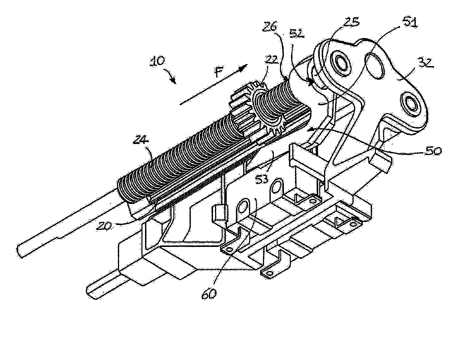
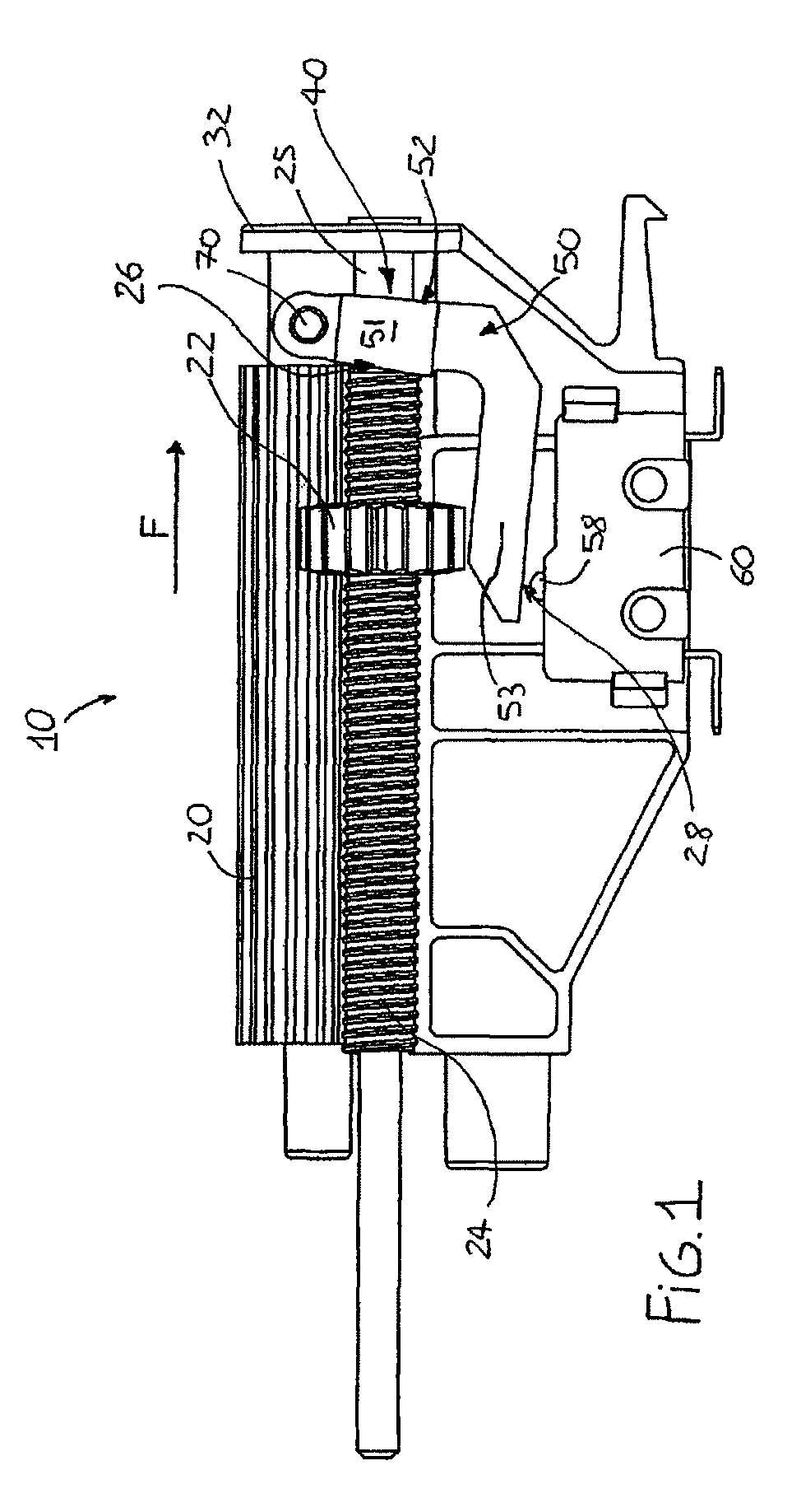
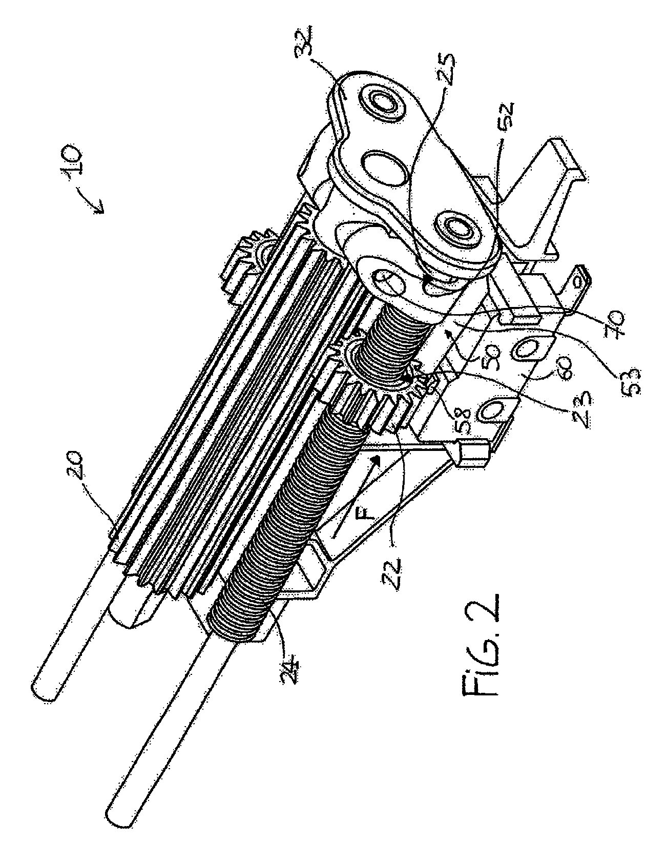
[0017]In the figures of the entire structure of the roller blind only the portion of interest in the region of the end-of-travel system is shown. With reference to the accompanying figures, a device according to the invention is denoted by 10. It normally and preferably consists of two identical end-of-travel devices which are arranged laterally alongside each other and only one of which for the sake of simplicity and brevity will now be described.

[0018]The device 10 comprises a rotating splined cylinder 20 mating with a gear wheel 22 which in turn engages, by means of its threaded central hole 23, with the thread of a fixed female screw 24 arranged parallel to the cylinder 20. Both the female screw 24 and the cylinder 20 are supported by a bracket 32 mounted on the frame of the roller blind (the other ends of the female screw 24 and the cylinder 20 are likewise supported by a similar bracket).

[0019]By means of a known mechanism, not shown, the motor for rotation of the roller blind...


PUM


Abstract

End-of-travel device (10) for roller blind actuating systems, comprising a member (22) displaceable as far as an end-of-travel position (26), coupling means (20) in engagement with the displaceable member (22) and rotationally actuated by a motor, and lever means (40) for converting the displacement of the displaceable member (22) into activation of an end-of-travel switch (60). The lever means (40) comprise a movable member (50) pivotably hinged on a frame and engageable with pressure by the displaceable member (22) when its reaches the end-of-travel position (26). The member (50) can be engaged with an actuating member (58) of the switch (60) where an actuating member of the switch (60) is positioned radially with respect to the axis of displacement of the member (22).

Description

BACKGROUND OF THE INVENTION[0001]The present invention relates to an end-of-travel device for actuating systems of roller blinds or sun shades, such as shutters, sun awnings, etc.[0002]It is known that in actuating systems for roller blinds (to which reference will be made henceforth for the sake of simplicity, but it being understood that the invention is not limited to this application) for some time automatic end-of-travel devices have been used, namely mechanical or electromechanical devices which cause stoppage of the roller blind when it reaches a predetermined final position.[0003]Many examples of these devices exist in the state of the art. In the patent FR 2,076,529 two gear wheels which advance on associated female screws act on end-of-travel switches (microswitches) displacing flanges which slide coaxially on a smooth portion of the female screws.[0004]In a very similar manner the patent EP 0,371,170 describes actuation of end-of-travel switches by means of gear wheels wh...

Claims


Application Information

Patent Timeline
IPC IPC(8): E06B9/40
CPCE06B9/88Y10T74/19684E06B2009/6881
Inventor MALAUSA, ANDREA
Owner NICE SPA
Why Eureka
Try Eureka