Method for manufacturing pneumatic tire

a pneumatic tire and manufacturing method technology, applied in the field of pneumatic tire manufacturing, can solve the problems of insufficient and difficult to achieve dimensional accuracy, and achieve the effect of molded accurately and sufficiently, accurate expansion and sufficient

a pneumatic tire and manufacturing method technology, applied in the field of pneumatic tire manufacturing, can solve the problems of insufficient and difficult to achieve dimensional accuracy, and achieve the effect of molded accurately and sufficiently, accurate expansion and sufficient

US7857926B2Inactive Publication Date: 2010-12-28SUMITOMO RUBBER IND LTD

Image

  • Method for manufacturing pneumatic tire
  • Method for manufacturing pneumatic tire
  • Method for manufacturing pneumatic tire

Examples


working example

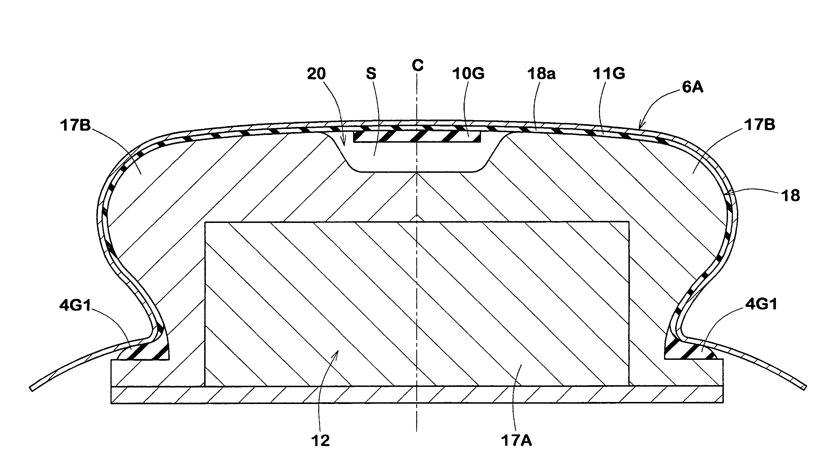
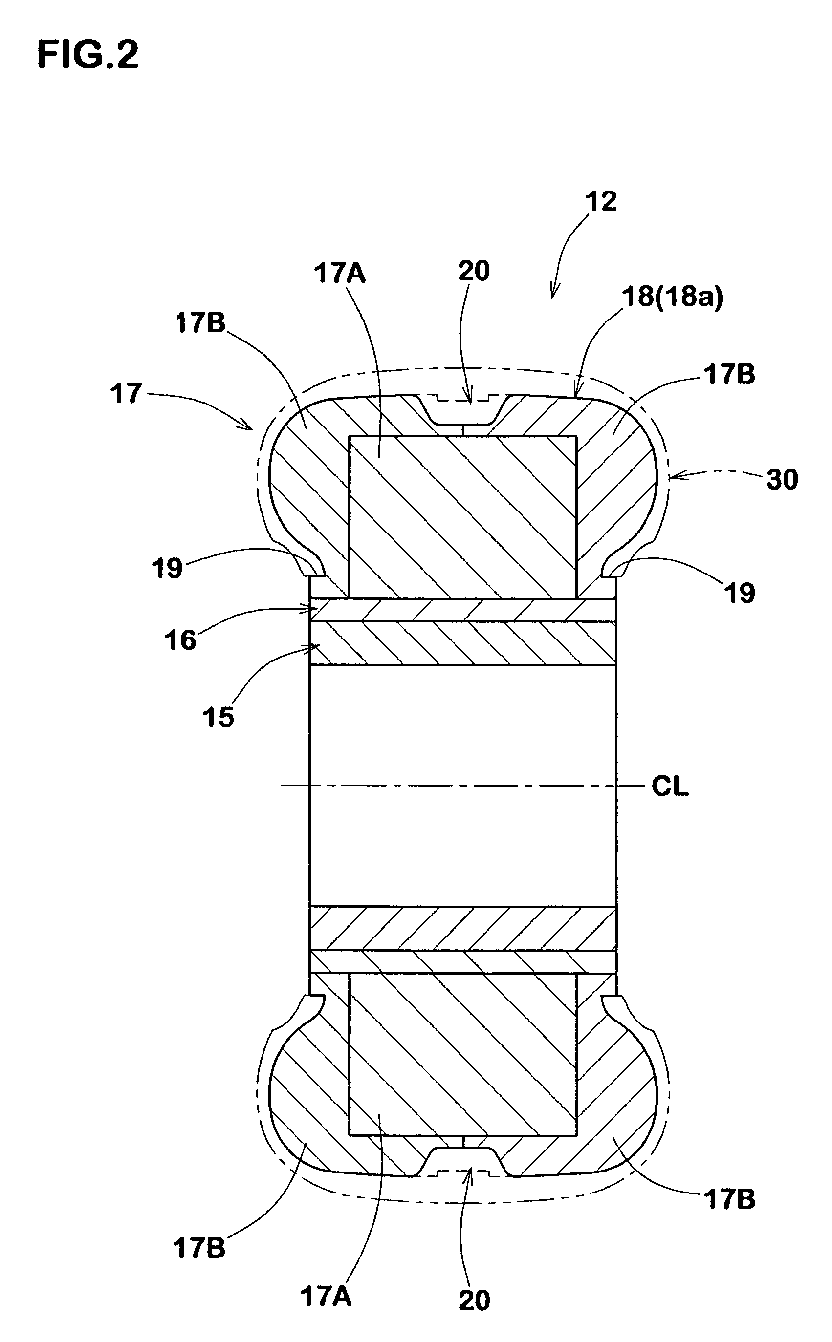
[0086]Using the tire building core 12 shown in FIG. 2, a radial tire for passenger cars was manufactured as illustrated in FIGS. 3, 4(A), 4(B), 6, 7 and 8.

[0087]

Tire size:195 / 65R15Carcass 6;a single ply of cords arranged radiallyat 90 degrees with respect to the tireequatorBelt:two cross ply steel breakerGroove 20:Maximum width6.0cmMaximum depth2.0cmVolume2,170ccExpandableShapeCircumferentiallydampercontinuous stripmaterial 10G:Width5.0cmThickness1.0cmVolume945ccCompositionas followsHalogenated butyl rubber50phrNR / IR35phrBR15phrCarbon black25phrMineral oil14phrSulfur0.6phrAccelerator1.8phrZinc oxide4phrStearic acid2phrTackifier resin2phrOBSH (blowing agent) *15phrUrea based blowing aid *22phr*1 “Celmike”, Sankyo Kasei Co., Ltd.*2 “Celton N”, Sankyo Kasei Co., Ltd.


PUM

PropertyMeasurementUnit
pressureaaaaaaaaaa
shapesaaaaaaaaaa
axial widthaaaaaaaaaa

Abstract

A method for manufacturing a pneumatic tire with a noise damper on the inside of the tread portion, comprises the steps of: building a raw tire on an annular tire building core; placing the raw tire within a vulcanizing mold together with the core; and heating the raw tire in the mold. The tire building core has a molding face for molding an inner surface of the tread portion. The molding face is provided with a groove extending in the tire circumferential direction. In the step of building the raw tire, an expandable damper material is placed in the groove. During heating the raw tire to be vulcanized, the damper material expands in the groove, whereby the expanded material forms the noise damper integrated into the radially inside of the tread portion.

Description

BACKGROUND OF THE INVENTION[0001]The present invention relates to a method for manufacturing a pneumatic tire provided on the radially inside of the tread portion with a noise damper, more particularly to a technique for molding the noise damper during vulcanizing the tire.[0002]Pneumatic tires provided on the radially inside of the tread portion with a noise damper made of foamed material has been proposed in order to damp resonance of air in the annular tire cavity. Thus, tire noise during running can be reduced.[0003]In the laid-open Japanese patent application No. 2003-285607, a method for manufacturing a pneumatic tire of this kind is disclosed, wherein an expandable material for the noise damper is applied to the inner surface of an unvulcanized tire; the unvulcanized tire is put in a mold; an inflatable bladder is set in the tire hollow; and the bladder is inflated during heating the tire to thereby mold and vulcanize the tire and at the same time expand the expandable damper...

Claims


Application Information

Patent Timeline
28 Dec 2010
Publication
US7857926B2
IPC
B29D30/16; B29D30/10
CPC
B29D30/0601; B29D30/0661; B29D30/0662; B60C19/002; B60C5/002; B29D30/12; Y10T152/10495
Inventors
NOBUCHIKA, HIDEO; SAKAMOTO, MASAYUKI