
Restraint with shoulder harness adjuster

a technology of harness adjuster and strap, which is applied in the field of straps, can solve the problem that the harness must be manually sized, and achieve the effect of reducing the number of straps

Inactive Publication Date: 2011-01-04
INDIANA MILLS MFG
View PDF23 Cites 52 Cited by
  • Summary
  • Abstract
  • Description
  • Claims
  • Application Information

AI Technical Summary

Problems solved by technology

A constant problem is that the harness must be manually sized depending upon the shape and size of the patient or child.

Method used


Image

  • Restraint with shoulder harness adjuster
  • Restraint with shoulder harness adjuster
  • Restraint with shoulder harness adjuster

Examples


second embodiment

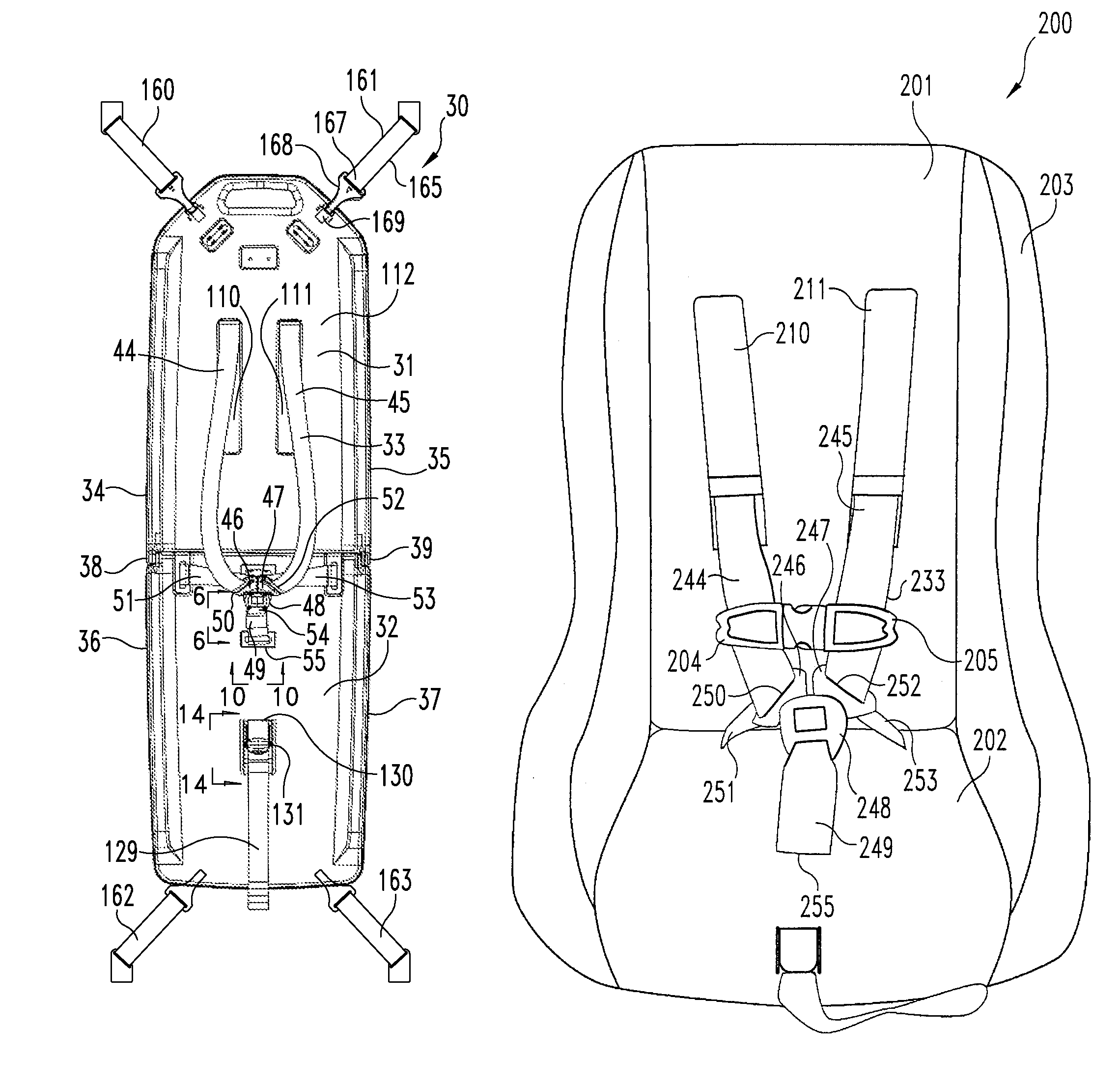
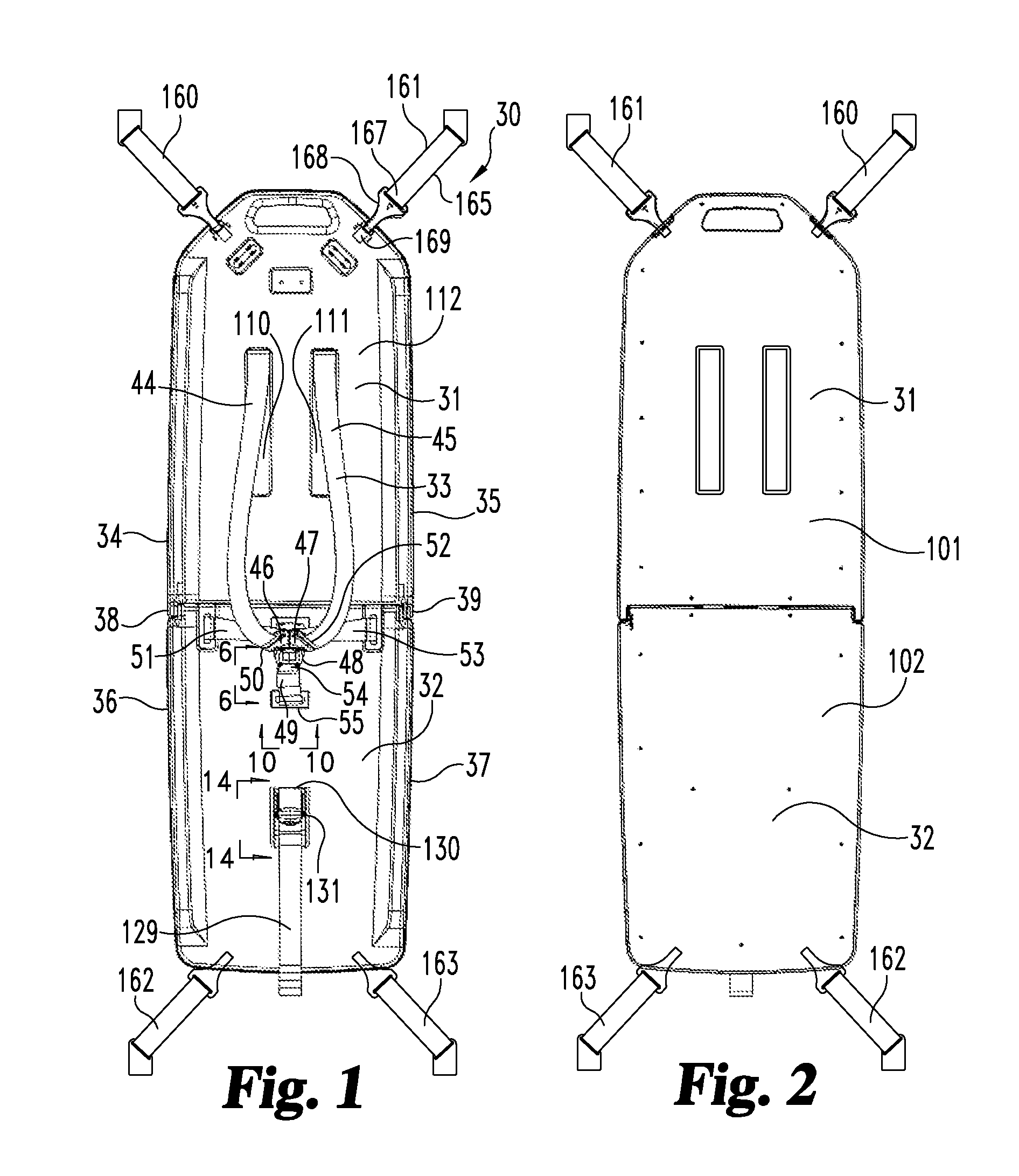
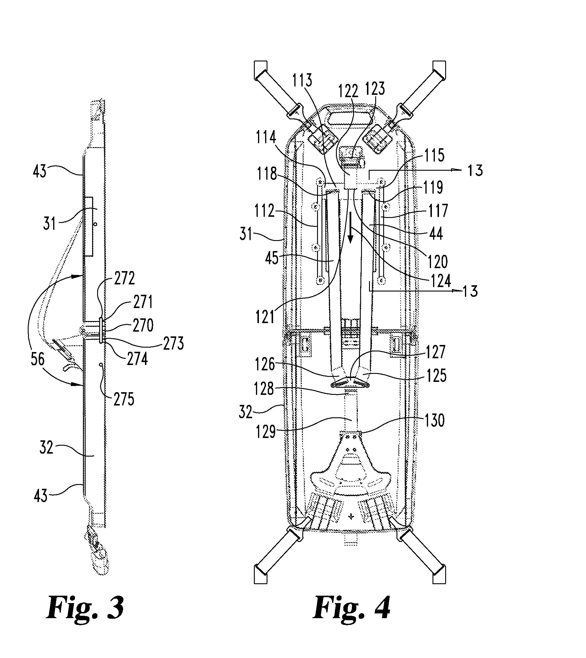
A second embodiment for mounting buckle 48 is shown in FIG. 7. Frame 60 of seat support 32 includes a pair of slots 71 and 72 with strap 49 first extending through slot 71 to beneath frame 60 and then back through slot 72 and through a web adjuster 73. By pulling strap 49 through web adjuster 73, the distance 69 of the buckle relative to the upwardly facing surface of seat support 32 may be controlled. A variety of web adjusters are commercially available. For example, U.S. Design Pat. D303,232 discloses one such web adjuster having a pivotable cam frictionally engaging the strap to hold the strap in place until the cam is pivoted to release the strap. U.S. Design Pat. D303,232 is herewith incorporated by reference. Another version of a web adjuster employs a push button to move the pivotable cam.

third embodiment

A third embodiment for mounting buckle 48 by strap 49 is shown in FIG. 8. Frame 60 includes a plurality of slots 74, 75 and 76 through which strap 49 is extendable being fixedly mounted to buckle 77 which may be identical to buckle 63 previously described. Frame 60 is indented at slot 75 and 76 with the indentation being deeper at the location of slot 76 as compared to the location of slot 75. In order to position the strap 49 at the locations of slots 75 and 76, buckle 77 may be pivoted so as to slide upwardly through slot 74 thereby disengaging strap 49 from slot 74. Buckle 77 can then be inserted edge wise through either slot 75 or 76 depending upon the desired location until the buckle is positioned beneath frame 60 as illustrated by the dashed line positions 78 and 79. In the embodiment shown in FIG. 8, the distance 69 between buckle 48 and the top surface of frame 60 is decreased when the strap and buckle is moved from the location of slot 74 to either slot 75 or slot 76. Like...


PUM


Abstract

A restraint for holding a person atop a gurney or on a vehicle seat. A harness includes a pair of straps slidably mounted to a main frame. The straps are connected to an adjuster. A slide plate is mounted to the frame with the straps extending therethrough. A spring loaded device normally positions the plate to position the straps apart from the shoulders of a person positioned beneath the straps until the straps are pulled relative to an adjuster moving the plate and the straps adjacent the shoulders of the person.

Description

BACKGROUND OF THE INVENTION1. Field of the InventionThe present invention relates generally to the field of restraints for holding a person on an emergency vehicle bed or a child seat positionable atop a vehicle passenger seat.2. Description of the Prior ArtA variety of harnesses are utilized to restrain patients on emergency gurneys and children atop vehicle seats. A constant problem is that the harness must be manually sized depending upon the shape and size of the patient or child. For example, in a five point harness assembly, the shoulder straps must be positioned to extend adjacent the person's shoulders and then tightened to limit movement of the person. A typical five point harness is shown in U.S. Pat. No. 5,158,337 which consists of a pair of lap belts, two opposite over-the-shoulder straps and a crouch strap which are connected together by a belt / tongue combination.Typically, in a five point harness assembly, the pair of shoulder straps extend through slots in the back su...

Claims


Application Information

Patent Timeline
Patent Type & Authority Patents(United States)
IPC IPC(8): A47B7/00
CPCA61G1/044B60N2/2812B60R22/20
Inventor AYETTE, MICHAEL W.DINGMAN, GUY R.
Owner INDIANA MILLS MFG
Learn More