Portable tire demounting tool

a portable, tire technology, applied in the field of tire tools, can solve the problems of inability to address some key factors, lack of functionality to adaptability, and the inherent limitations of the current method and apparatus for tire demounting

Inactive Publication Date: 2011-01-04
OCHOA ROADRUNNER PRODS
View PDF14 Cites 4 Cited by
  • Summary
  • Abstract
  • Description
  • Claims
  • Application Information

AI Technical Summary

Benefits of technology

Disclosed is a hand operated demounting tool. A handle, preferably a cylindrical member, of adequate length provides sufficient leveraging pressure and mechanical advantage to the tire bead during the demounting procedure. The handle accommodates gripping positions along its length for an operator to grip the tool during the demounting procedure. At one end it can have a molded plastic or rubber grip. On the second end is an open spanning element. This element consists of a yoke connected, and running substantially perpendicular to the length of the handle. On either side of this yoke assembly are two upright members running substantially parallel to the handle. This facilitates the spanning of the wheel center on reverse wheel assemblies where the cup of the wheel is to the topside of the demount position by allowing an increased prying stroke.
Another advantage of the presently claimed invention is that it ensures that the bead on the opposite side of the demount tool is successfully guided into the drop center of the wheel assembly.

Problems solved by technology

With the wide range of composite materials, sizes, bead shapes, and methods of manufacture for tire and wheel assemblies, there are a number of inherent limitations to the current methods and apparatuses for tire demounting.
These limitations range from functionality to adaptability.
They fail to address some key factors in the successful removal of a tire from the rim or wheel assembly.
The functionality of the prior art systems for demounting tires is limited in a number of ways.
This results in damage and tearing of the tire bead while trying to remove the tire from the wheel.
The construction of low profile tires also is a limiting factor for many of the current tools.
These low profile sidewalls and the use of multi-ply steel or fiber construction, make these tires stiff and difficult to work with.
Power operated devices tend to tear and ruin the bead of these types of tires.
Hand tools often prove ineffective, having neither the shape to conform to such tires or the prying force to extract it from the rim or wheel.
Removal of these tires with the current devices results in damaging the tire beyond repair, and, thus, defeating the purpose of repairing and remounting the tire.
A further limiting factor for many of the current tools is removal of soft side wall tires with a highly pliable bead.
These tires present the problem of having a bead that stretches, but becomes difficult to extract from the wheel.
Disengaging the tool from this area will cause the elastic bead to return to its original position, thus failing to remove the tire from the rim.
The narrow hand operated spoons and pry bars are especially susceptible to this malfunction, and there is often the added consequence of bead tearing.
The current conventional hand tire demounting tools fail in their adaptability because they are confined to being used with specific sized tires and wheel assemblies.
Power type tools are also limited in their range of size, type of wheel, and tire assemblies to work effectively.
The power operated tools are further limited in their ability to work in remote locations away from air, electric, hydraulic or other power sources.
This type of hub center limits the leveraging stroke of the current pry bar type tools to such a degree that they are ineffective.
Finally, these prior art methods, whether power or hand operated tire demounting systems, fail to address a key issue in the successful demounting of a tire from its rim assembly, namely the manipulation of the bead into a shallow channel that is referred to as the drop center of the wheel assembly during the demounting procedure.
The prior art methods, whether power or hand operated tire demounting systems, have no mechanical means to ensure that the bead is in the drop center, thereby allowing undue pressure to be placed on the tire bead during demounting and causing further damage to the bead or resulting in an unsuccessful demounting procedure.

Method used


Image

  • Portable tire demounting tool
  • Portable tire demounting tool
  • Portable tire demounting tool

Examples


second embodiment

FIG. 12 is a side cut away view of tire demount tool 100 for light truck, trailer, and automotive tires inserted into first bead 138 of tire 140 and wheel assembly 150 in the early stage of operation. Prying foot 118 is inserted between the top of rim flange 136 and first bead 138 of tire 140. Dual rim hooks 132 are positioned to reach below and past rim flange 136 on engagement hooks 144. Tool 100 is now properly inserted and in position for the removal of first bead 138. FIG. 12 further illustrates the use of drop center bead wedge 170 in operation. Drop center bead wedge 170 is secured in place with a downward motion of pressure applied on the top side of rim retainer 152, on an opposite side of tire demount tool 100, as shown. Wedge spacer 154 and side wall skid 156 force first bead 138 and top tire side wall 148 into the drop center 160 of wheel assembly 150 effectively allowing for free movement of first tire bead 138 during the demounting process.

FIG. 13 is a side cut away vi...

third embodiment

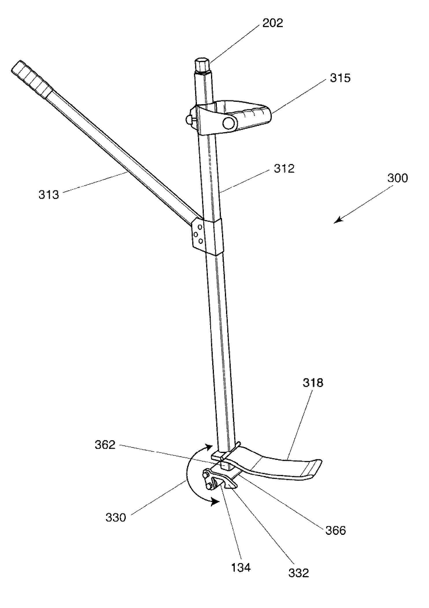
FIG. 14 is a side view and FIG. 15 is a perspective view of retractable screw assembly 200 for the mechanically retractable tire demount tool 300. The preferred embodiment of retractable screw assembly 200 consists of a hex head threaded drive bolt 202, a flat washer 204, a square weld-in block bushing 206, a bushing retainer 208, and a weld-in threaded block nut 210. Retractable screw assembly 200 is the drive mechanism for demount tool 300.

FIG. 16 is a side view and FIG. 17 is a perspective view of a third embodiment of a retractable, tire demount tool 300. This embodiment is useful for the removal of the second or lower bead. These tires tend to be harder to manage and result in tearing or stretching the bead to render the tire useless. The use of this embodiment removes the first bead easily by peeling the bead off with no bead tearing or undue bead stretching, thus, preventing ruining of the tire. Retractable tire demount tool 300 consists of a hollow handle portion 312, connec...

fourth embodiment

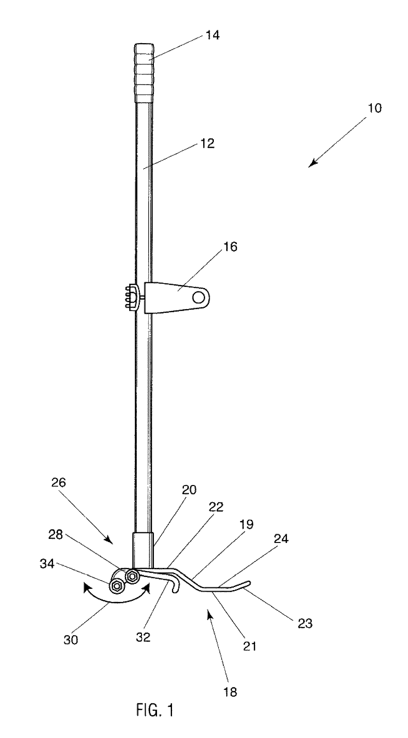
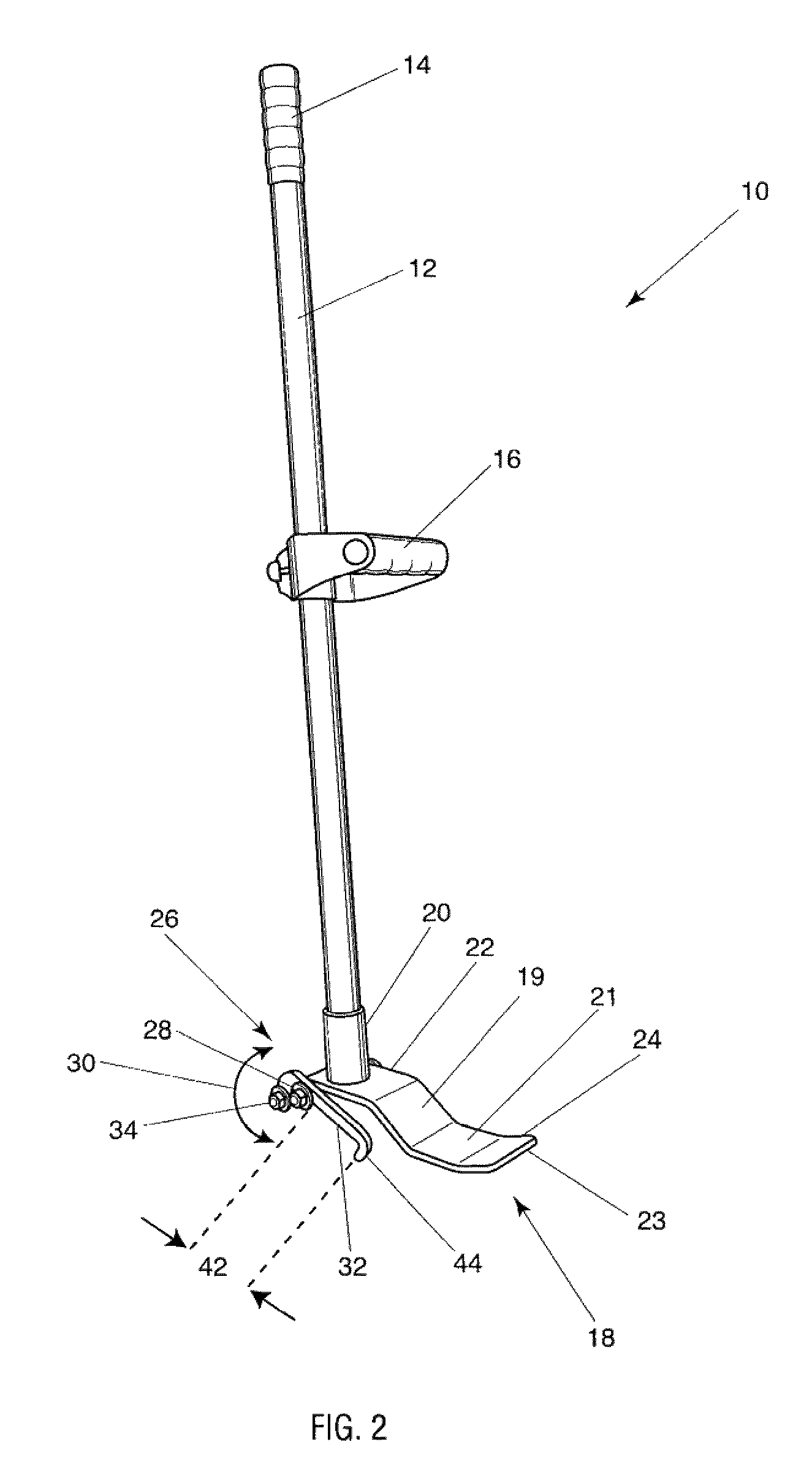
This fourth embodiment retractable tire demount tool for first bead 400 has a fixed pivot rim hook 432. Fixed pivot rim hook 432 provides a fixed position by which to cam the tool over providing an optimum point by which to engage the retractable drive bolt 202 and thereby remove the tire from the wheel assembly. Fixed pivot hook 432 is a “J” shaped member 435 on the inner portion for engaging and securing the rim flange when the telescoping function is engaged. Fixed pivot hook 432 has a spear shaped configuration 433 to aid in inserting it between the tire bead and the wheel assembly.

As in the aforementioned embodiments, demount tool 400 is inserted between rim or wheel assembly 450 and tire 440 by inserting shortened prying foot 418 into the interior of tire onto upper tire side wall 456 and engaging the same. Fixed pivot foot 432 is hooked to rim flange 426 by engaging “J” shaped member 435, as shown, thus readying the demount procedure. Fixed pivot foot 432 can have a spear sha...


PUM


Abstract

A method and apparatus for demounting tires from wheel assemblies with a hook assembly and a prying foot. One tool has two holding hooks that grasp the tool to the wheel and a foot that is attached to the holding hooks, and a bearing pivot point that allows the demounting tool to easily and safely remove the tire from the wheel. The tool can be used for all types of tire and wheel types. One tool is for large truck and trailer tires and a second too is for light truck, trailer and automobile tires. A third tool is designed for low profile, stiff sidewall tires and includes a telescoping structure to raise and lower the dual hooks. A forth embodiment is for demounting a first and second bead using a fixed pivot hook, sized prying feet and a telescoping assembly for pulling the bead from the wheel assembly.

Description

BACKGROUND1. Field of the Invention (Technical Field)The presently claimed invention generally relates to tire tools and more particularly to hand operated portable tire demounting tools and assisting components thereof.2. Background ArtThere is a large variety of hand operated and power assisted tire demounting tools on the market. They range from simple pry bars too geometrically complex leveraging devices, along with power operated demounting devices.With the wide range of composite materials, sizes, bead shapes, and methods of manufacture for tire and wheel assemblies, there are a number of inherent limitations to the current methods and apparatuses for tire demounting. These limitations range from functionality to adaptability. They fail to address some key factors in the successful removal of a tire from the rim or wheel assembly.The functionality of the prior art systems for demounting tires is limited in a number of ways. Many conventional pry spoons and bars are made with a...

Claims


Application Information

Patent Timeline
Patent Type & Authority Patents(United States)
IPC IPC(8): B60C25/02
CPCB60C25/04
Inventor OCHOA, SANDY
Owner OCHOA ROADRUNNER PRODS
Why Eureka
Try Eureka