
Steering column device with knee airbag device

a technology of knee airbags and steering columns, which is applied in the direction of steering parts, vehicle components, pedestrian/occupant safety arrangements, etc., can solve the problems of not being able to form an airbag door, and being more difficult to wide open the airbag door, so as to facilitate the execution of control and increase the length of the steering column.

Inactive Publication Date: 2011-01-04
TOYOTA JIDOSHA KK
View PDF23 Cites 54 Cited by
  • Summary
  • Abstract
  • Description
  • Claims
  • Application Information

AI Technical Summary

Benefits of technology

The invention is a steering column device with a knee airbag device that can be widely opened in cases where the design of the instrument panel or the position of the steering wheel restricts the movement of the airbag door. The device includes a column cover, an airbag module, an airbag door, and a collision prediction device. When the collision prediction device predicts a collision, the control device operates the telescopic mechanism to move the column cover and airbag module rearward to a predetermined position, allowing the airbag door to open without interfering with the instrument panel or the position of the steering wheel. The telescopic mechanism is an electric telescopic mechanism driven by a telescopic motor, which makes it easy to control the movement of the airbag door. The invention allows for a quick increase in the length of the steering column and increases the area where the airbag door is opened.

Problems solved by technology

However, in the above-described technology, in the case where the airbag module overlaps the outline of an instrument panel in a lateral view when the knee airbag device is provided in a vehicle, it is not possible to form an airbag door that extends in the lower surface and side surfaces of the column cover so that the airbag door is widely opened.
Therefore, it is more difficult to widely open the airbag door.
Further, the same problem occurs also in the case where a steering wheel is placed at a front position in the direction of the axis of a steering column in the steering column device provided with a telescopic mechanism.

Method used


Image

  • Steering column device with knee airbag device
  • Steering column device with knee airbag device
  • Steering column device with knee airbag device

Examples


Embodiment Construction

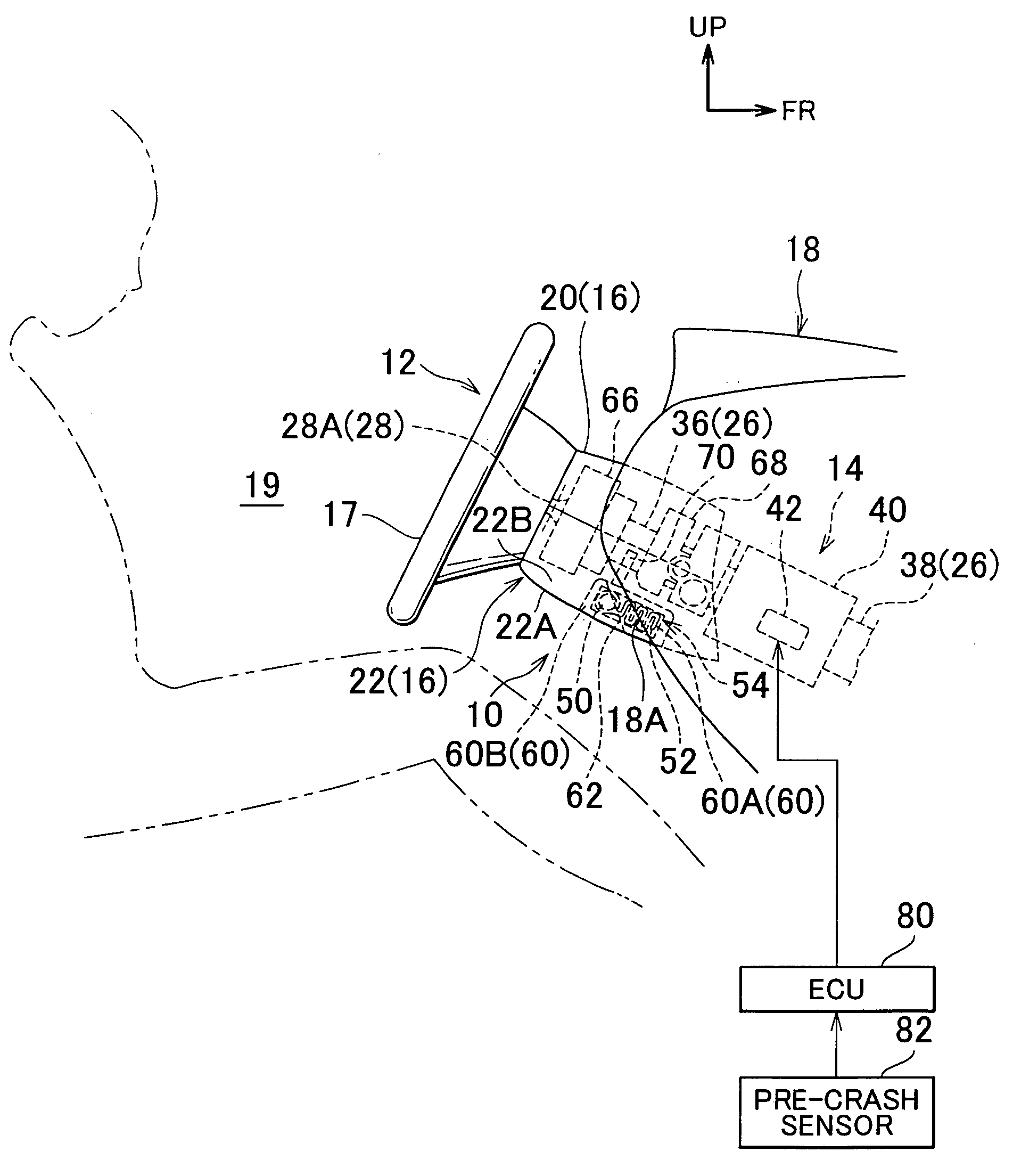
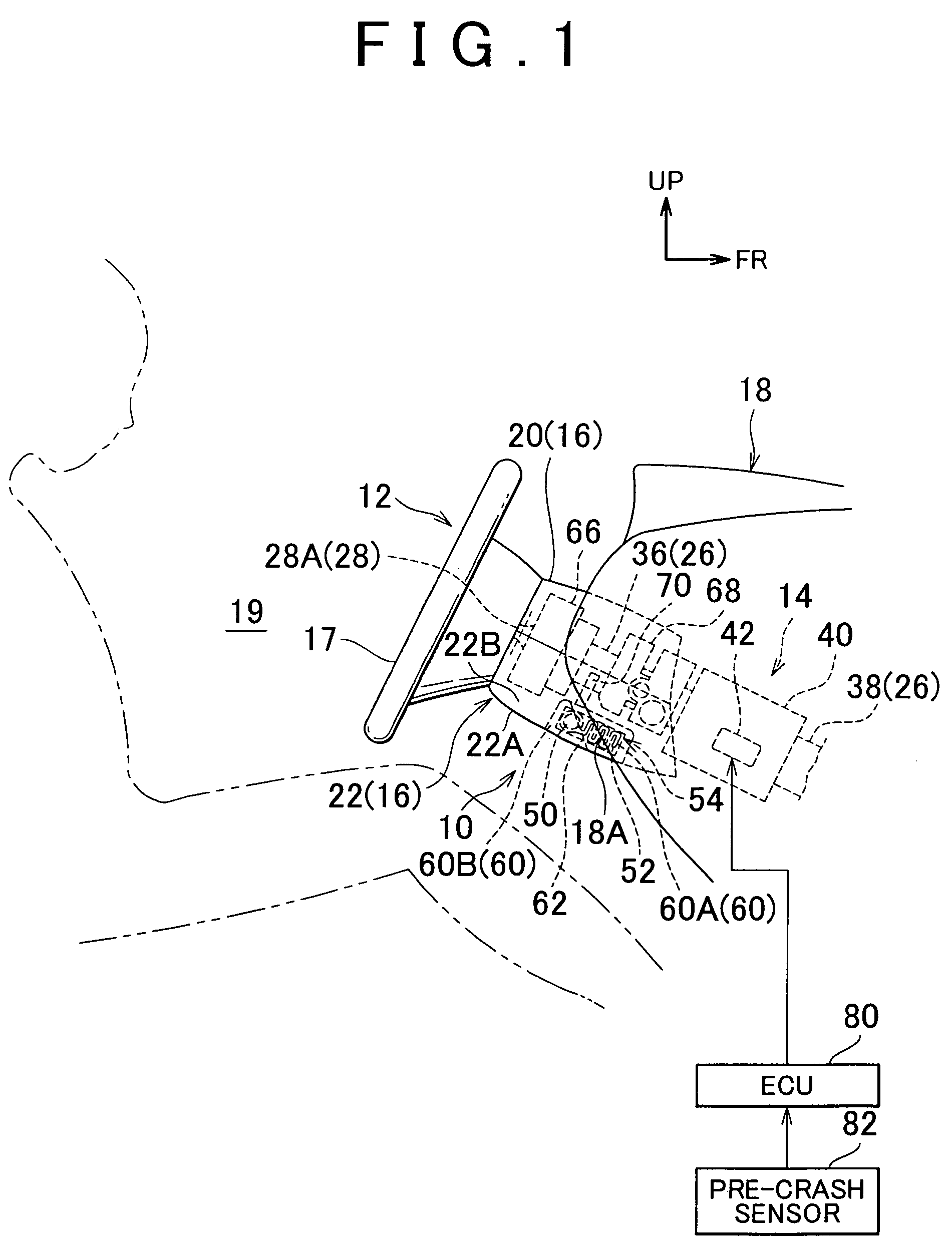
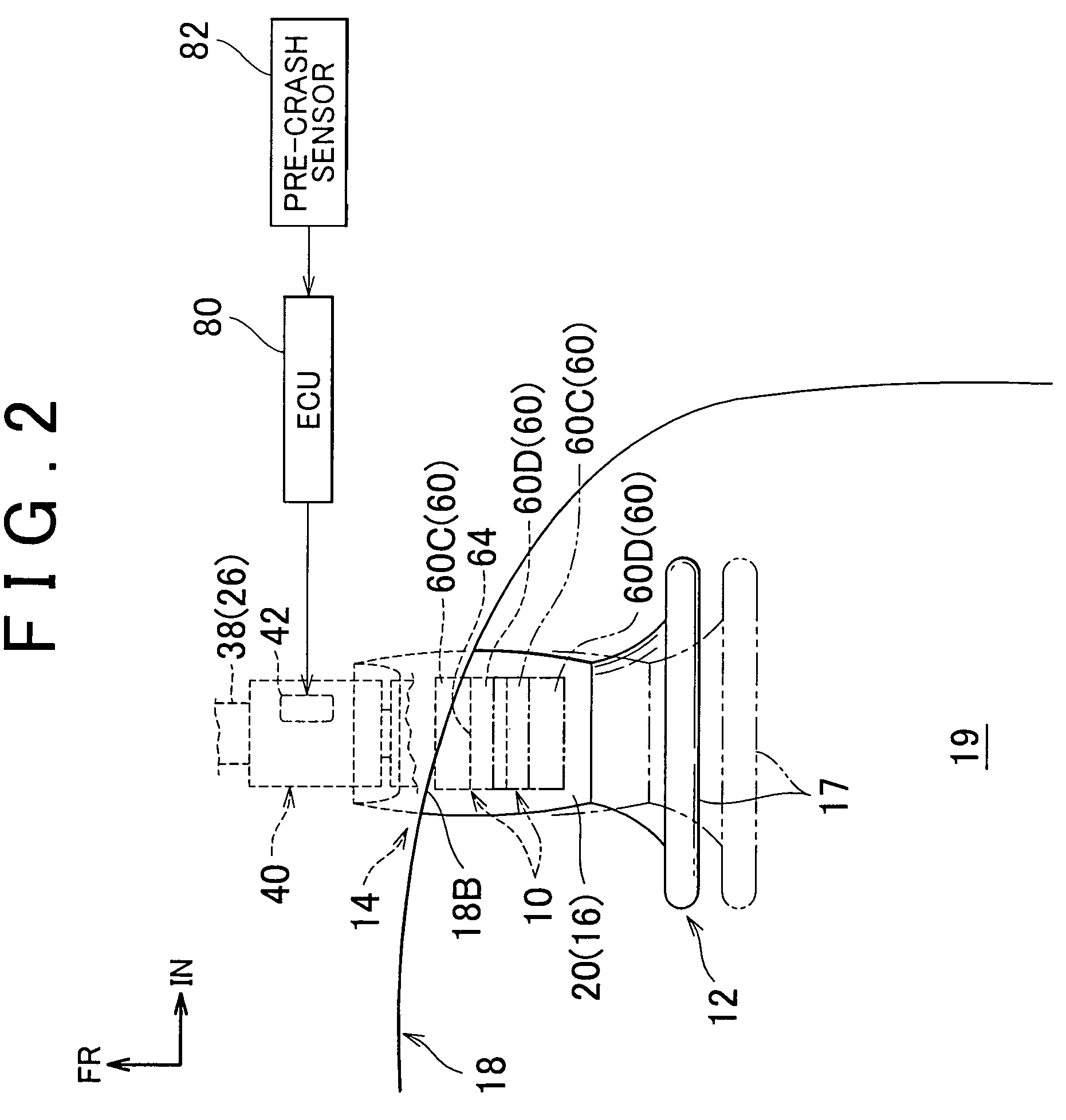
[0019]Hereinafter, a steering column device with a knee airbag device according to an embodiment of the invention will be described with reference to FIG. 1 to FIG. 3. In FIG. 1 to FIG. 3, the arrow FR indicates the front of a vehicle. The arrow UP indicates the top of the vehicle. The arrow IN indicates the inside of the vehicle in a vehicle-width direction.

[0020]FIG. 1 is a lateral view showing the entire configuration of a steering column device 12 with a knee airbag device 10 according to the embodiment of the invention. FIG. 2 is a plan view showing the steering column device 12 with the knee airbag device 10. Further, FIG. 3 is a lateral view showing the steering column device 12 with the knee airbag device 10, which is operated. In the embodiment, the steering column device 12 with the knee airbag device 10 is installed in a left-hand drive vehicle.

[0021]As shown in FIG. 1 and FIG. 2, the steering column device 12 includes a steering column body 14, a column cover 16 that cov...


PUM


Abstract

A steering column device with a knee airbag device includes a steering column provided with a telescopic mechanism; a column cover that covers the rear end portion of the steering column; an airbag module, provided inside the column cover, which includes a gas generation device that generates gas, and a knee airbag that is inflated and deployed by the gas; an airbag door that is provided in the column cover, and that is opened when the airbag door receives the inflation pressure of the knee airbag; a collision prediction device that predicts that a vehicle will have a collision with a collision object; and a control device that operates the telescopic mechanism so that each of the column cover and the airbag module is moved rearward to a predetermined position, when the collision prediction device predicts that the vehicle will have a collision with the collision object.

Description

INCORPORATION BY REFERENCE[0001]The disclosure of Japanese Patent Application No. 2007-060202 filed on Mar. 9, 2007 including the specification, drawings and abstract is incorporated herein by reference in its entirety.BACKGROUND OF THE INVENTION[0002]1. Field of the Invention[0003]The invention relates to a steering column device with a knee airbag device that includes a knee airbag that is inflated and deployed to restrain knees of an occupant when a collision occurs, and when it is predicted that a collision will occur.[0004]2. Description of the Related Art[0005]Various knee airbag devices have been proposed to protect the knees of an occupant. For example, each of Japanese Patent Application Publication No. 9-104317 (JP-A-9-104317) and Japanese Patent Application Publication No. 9-123862 (JP-A-9-123862) describes a knee airbag device that includes an airbag module disposed inside a column cover for a steering column.[0006]However, in the above-described technology, in the case ...

Claims


Application Information

Patent Timeline
Patent Type & Authority Patents(United States)
IPC IPC(8): B60R21/203B62D1/11B60R21/05B60R21/20B60R21/206B62D1/18B62D1/181
CPCB60R21/2032B60R21/206B62D1/197B60R21/2165B60R2021/23107B60R2021/23169
Inventor FUKAWATASE, OSAMUIMAMURA, KENJISANADA, AKIYOSHIADACHI, YUICHIBITO, KAZUAKI
Owner TOYOTA JIDOSHA KK
Learn More