Open bridge rack

a technology of open bridge and equipment rack, which is applied in the field of equipment racks, can solve the problems of limiting the placement and orientation of individual electronic components within the equipment of the equipment, affecting the operation efficiency of the equipment, and generating heat from redundancy power converters, etc., and achieves the effects of convenient configuration, improved airflow management, and easy conversion

Active Publication Date: 2015-04-02
FMR CORP
View PDF13 Cites 26 Cited by
  • Summary
  • Abstract
  • Description
  • Claims
  • Application Information

AI Technical Summary

Benefits of technology

[0007]There is a need for an equipment rack that can be used for mounting currently-owned EIA-compatible IT equipment, but can be easily configured to be used for mounting next-generation OCP-compatible equipment. One advantage of the equipment rack of the present disclosure is that it provides a single equipment rack that can bridge the gap between the standard EIA 19″ rack design and the developing OCP Open Rack design, with an ability to convert from one standard to the other. Another advantage of the equipment rack of the present disclosure is that it can be easily converted from an EIA-compliant equipment rack to an OCP-compliant equipment rack without having to be physically relocated. Another advantage of the equipment rack of the present disclosure is that it provides a wider opening to mount IT equipment in the OCP configuration, and fits more IT equipment per volume. Another advantage of the equipment rack of the present disclosure is that it provides better airflow management for cooling IT equipment mounted in the equipment rack. Another advantage of the equipment rack of the present disclosure is that it can disaggregate power from the rack itself.

Problems solved by technology

The redundant power converters generate a significant amount of heat and have a low overall operating efficiency.
Furthermore, the 19″ front panel width specification of the EIA standard limits the possible placement and orientation of individual electronic components within IT equipment.
As a result, complicated airflow management schemes are required to maintain safe operating temperatures for all rack-mounted IT equipment.
The difference in specifications between the EIA-compliant equipment rack and the OCP-compliant equipment rack make them incompatible, i.e., an OCP-compliant equipment rack cannot be used to mount IT equipment designed to be mounted in a 19″ EIA-compliant rack and vice-versa.

Method used


Image

  • Open bridge rack
  • Open bridge rack
  • Open bridge rack

Examples


Embodiment Construction

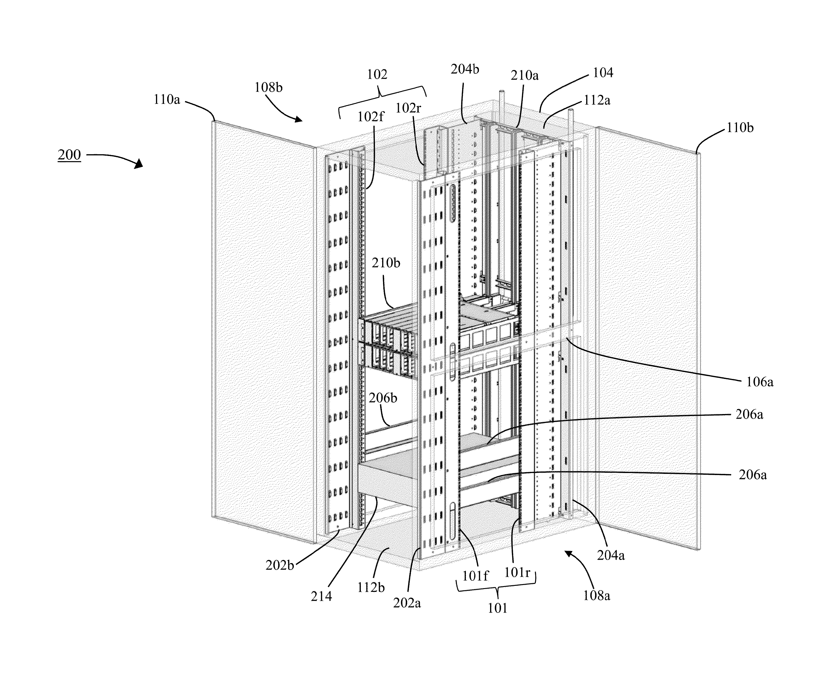
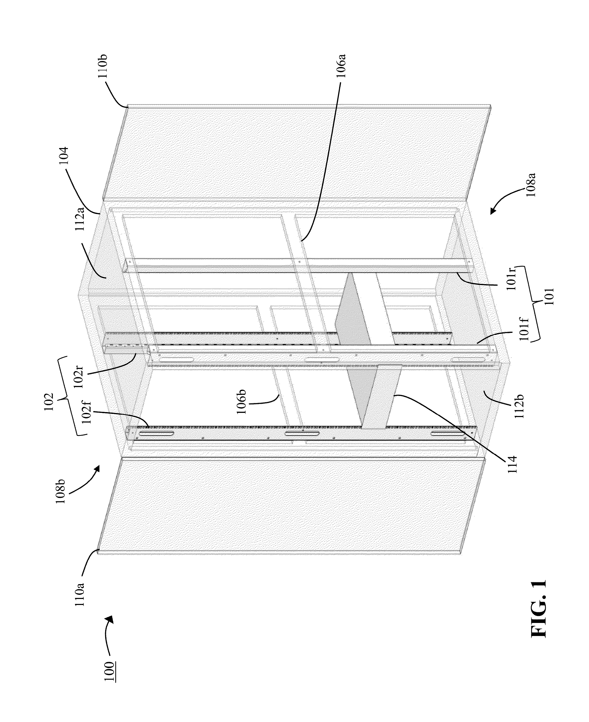
[0033]FIG. 1 shows a perspective view of an EIA-compliant equipment rack 100 in accordance with embodiments of this disclosure. The overall dimensions of rack 100 can vary according to vendor or customer preferences. In some embodiments, the overall dimensions of rack 100 are 28″ wide×48″ deep×83″ high. Rack 100 includes a frame 104, comprising vertical and horizontal members that are coupled together. The frame 104 can include an upper section and a lower section, each comprised of four horizontal beams coupled together and forming a rectangle. The frame 104 can further include four vertical supports with each end coupled to a corresponding corner of the upper and lower sections. As shown in FIG. 1, the frame 104 includes a first horizontal strut 106a coupled between the vertical supports on a first side 108a (e.g., right side) of the frame 104, and a second horizontal strut 106b coupled between the vertical supports on a second side 108b (e.g., left side) of the frame 104. In some...


PUM

PropertyMeasurementUnit
widthaaaaaaaaaa
widthaaaaaaaaaa
vertical linear distanceaaaaaaaaaa

Abstract

An equipment rack includes a frame, a first pair of mounting rails and a second pair of mounting rails. Each pair of mounting rails includes a front mounting rail and a rear mounting rail and the front and rear mounting rails each include a first planar surface defining in part a first equipment-mounting interface when the front and rear mounting rails are coupled to the frame through a second planar surface of each of the front and rear mounting rails in a first configuration. The front and rear mounting rails each further include a third planar surface and a fourth planar surface defining in part a second equipment-mounting interface when the front and the rear mounting rails are coupled to the frame through the first planar surface in a second configuration. The first and second equipment-mounting interfaces can be defined by an equipment rack standard.

Description

RELATED APPLICATIONS[0001]This application claims priority to U.S. Provisional Patent Application No. 61 / 884,853, filed Sep. 30, 2013, the entirety of which is incorporated herein by reference.FIELD OF THE INVENTION[0002]The subject matter of this application relates generally to equipment racks, and more particularly to Information Technology (“IT”) equipment racks that can be configured to support multiple equipment rack standards.BACKGROUND[0003]Equipment racks are used extensively for mounting Information Technology (“IT”) equipment. Equipment racks typically include a frame and / or an enclosure with two or four vertical posts provided to which IT equipment is mounted. Several formal standards exist which dictate the specifications of particular equipment racks. For example, equipment rack standards commonly specify an incremental equipment height value or Rack Unit (“RU”), a vertical mounting hole spacing, a rack equipment opening width, and a width value for the front panel of ...

Claims


Application Information

Patent Timeline
Patent Type & Authority Applications(United States)
IPC IPC(8): H05K7/18A47B96/14A47B46/00A47B47/00
CPCH05K7/18A47B46/00A47B96/1416A47B47/0083H05K7/1488Y10T29/49826A61M31/002A61M31/007C07D207/48C07D211/96C07D277/06C07D401/12C07D403/12C07D409/12C07D413/12C07D417/12C07D471/04
Inventor OBERNESSER, BRIANCLARK, JR., DALE B.
Owner FMR CORP
Why Eureka
Try Eureka