Device for the ventilation of the crankcase of an internal combustion engine

a technology for internal combustion engines and crankcases, which is applied to internal combustion piston engines, engine components, and non-fuel substance addition to fuel, etc., can solve the problems of reducing the efficiency of the oil-mist separator, the danger of excess pressure developing in the crankcase, and the operation drawbacks, so as to reduce the load on the suction pump and the drive motor, and the service life is unlimited

Inactive Publication Date: 2006-09-05
HENGST WALTER
View PDF11 Cites 27 Cited by
  • Summary
  • Abstract
  • Description
  • Claims
  • Application Information

AI Technical Summary

Benefits of technology

[0006]In case of the apparatus according to the invention, the pump unit ensures, to its advantage, that there is always a desired vacuum pressure in the crankcase of the combustion engine, with this vacuum pressure being maintained even in such operating states of the combustion engine that do not permit generation of the appropriate vacuum pressure only via the intake pipe. At the same time, the pump unit ensures an adequately high volume flow at the crankcase ventilation gas through the oil-mist separator, so that the latter has a high efficiency in any operating state of the combustion engine.
[0024]As an alternative to controlling the effective power of the pump unit, a bypass duct can be connected to a regulating valve together with the vent line, with this bypass duct short-circuiting the pump unit and this regulating valve being adjustable according to the crankcase pressure. This ensures that closed-circuit delivery of the ventilation gas through the pump unit and the associated bypass duct can be achieved if required, whereby the effective power of the pump unit can be controlled as desired with regard to the crankcase ventilation gas delivered from the crankcase into the intake pipe. The wider open the regulating valve, the lower the effective power of the pump unit, and vice versa.

Problems solved by technology

Known apparatuses of the said type have various operational drawbacks that are, in particular, incurred in certain operating states.
A drawback of spark-ignition engines is that the drop in pressure above the oil-mist separator is relatively high and causes the danger of an excess pressure developing in the crankcase if the difference between the vacuum pressure in the intake pipe and the atmospheric pressure is inadequate.
Moreover, this results in a reduced efficiency of the oil-mist separator because in spark-ignition engines, use is normally made of separators that are operated by the principle of inertia and require a high efficiency to ensure an adequately high volume flow.
Another drawback is incurred whenever the combustion engine is in its no-load range because, in this state, the pressure developing in the crankcase may become too high.
This problem is, in particular, arising in case of advanced combustion engine wear because this may lead to high blow-by volume flows at high speed and no-load.

Method used


Image

  • Device for the ventilation of the crankcase of an internal combustion engine
  • Device for the ventilation of the crankcase of an internal combustion engine
  • Device for the ventilation of the crankcase of an internal combustion engine

Examples


first embodiment

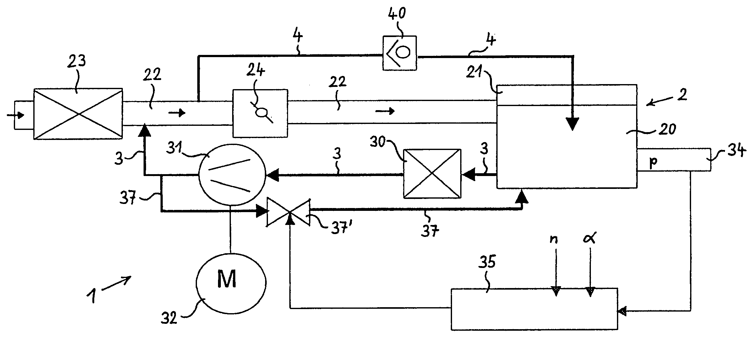
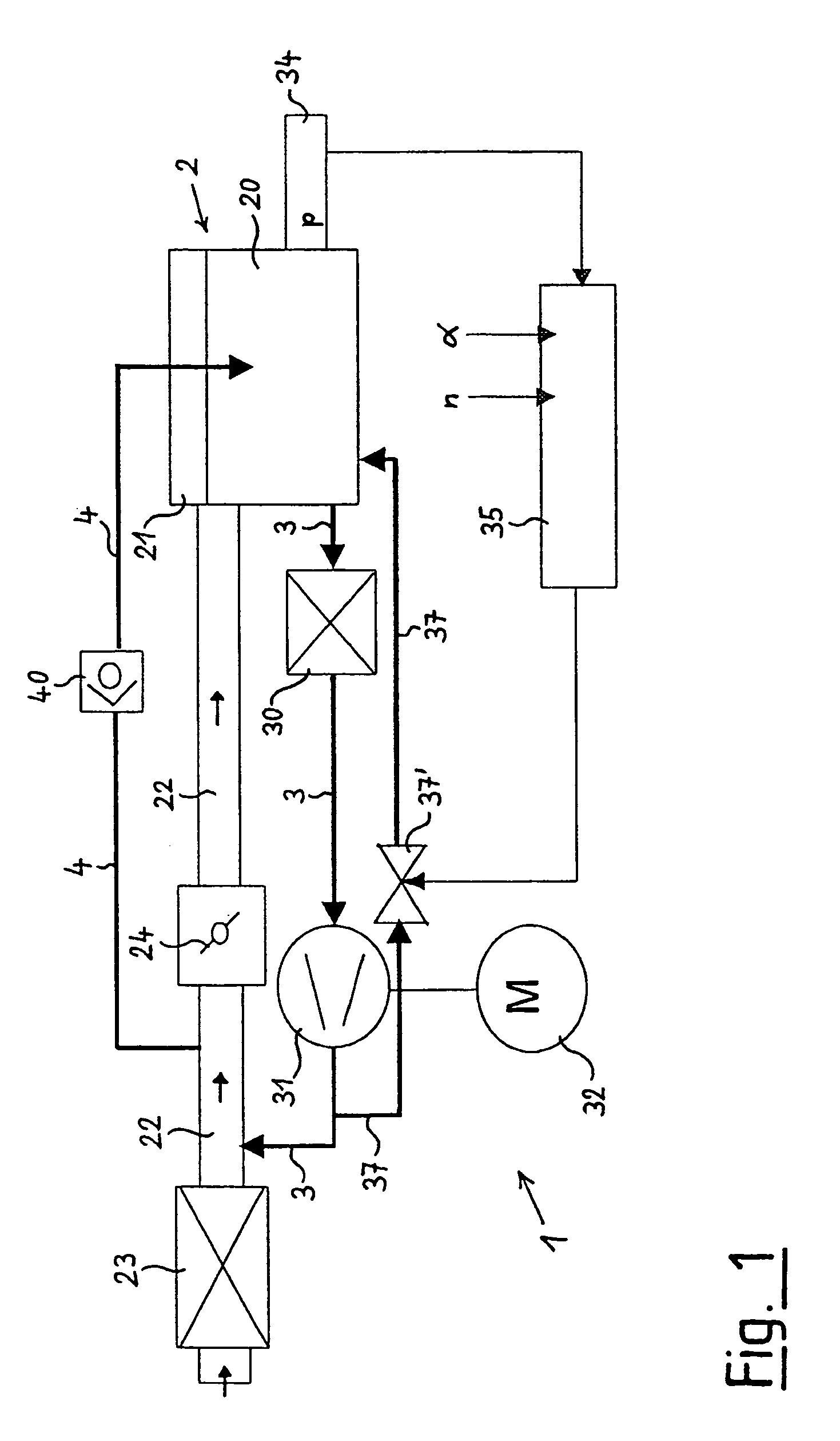
[0041]The bypass line 37 running from the pump 31 to the crankcase 20 in the apparatus 1 is not applicable; instead, a branch line 38 branches off from the vent line 3 to the pump unit 31 at a point upstream of the oil-mist separator 30 and, via a regulating valve 38′, ends in the intake pipe 22 at a point downstream of the throttle valve 24. A further difference is that, in this case, the check valve 40 in the vent line 4 is combined with a remote-controllable shut-off valve 41.

[0042]In its remaining parts, the apparatus according to FIG. 2 is identical with the embodiment shown in FIG. 1.

[0043]The regulating valve 38′ in the branch line 38 running from the outlet of the oil-mist separator 30 to the intake pipe 22 downstream of the throttle valve 24 is adjusted by the regulator 35 according to the pressure p in the crankcase, the crankshaft speed n and the throttle valve position α. Herein, the position of the valve 38′ is adjusted such that the valve 38′ is in the open position wh...

third embodiment

[0045]FIG. 3 of the drawing shows the apparatus 1, differing from the embodiment according to FIG. 2 in two additional elements. These additional elements are, on the one hand, a branching valve 39′ that is incorporated downstream of the pump unit 31 in that section of the vent line 3 that is running to the intake pipe 22. A return line 39 is running from the branch outlet of the branching valve 39′ to the crankcase 20.

[0046]The second additional element is the fact that, in this embodiment, the pump unit 31 is power-controlled. To achieve this, the regulator 35 is likewise designed as an electric switch or voltage regulator that is adjusted according to the pressure p in the crankcase, the crankshaft speed n and the throttle valve position α. The regulator 35 acts upon the performance of the engine in a controlling manner, thus regulating the power of the pump unit 31.

[0047]In its basic operating state, the apparatus 1 according to FIG. 3 is operated in the same ways as is the appa...


PUM


Abstract

The invention relates to a device (1), for the ventilation of the crankcase (20) of an internal combustion engine (2), with a breather tube (3), running from the crankcase (20) to an inlet manifold (22) on the internal combustion engine (2), in the course of which an oil-mist separator (30) is arranged. The novel device is characterized in that in the course of the breather line (3), a pump device is arranged, by means of which a reduced pressure may be generated in the crankcase (20) relative to ambient pressure.

Description

BACKGROUND OF THE INVENTION[0001]The present invention relates to an apparatus for ventilating the crankcase of a combustion engine, comprising a vent line running from the crankcase to an intake pipe of the combustion engine and an oil-mist separator that is arranged in the course of the vent line.[0002]An apparatus of the said type is known from the practice of engine construction, in particular for automobiles. This apparatus aims at maintaining in the crankcase of the combustion engine a vacuum pressure that is required for technical and legal reasons by ventilating the crankcase; to achieve this, gases or, in particular, blow-by gases are conducted out of the crankcase or the combustion chambers of the combustion engine to the intake pipe of the engine. Any oil contents carried in the crankcase ventilation gas are separated in an oil-mist separator; preferably, the separated oil is supplied to the lubricating oil circuit of the combustion engine again. The gas that has been fre...

Claims


Application Information

Patent Timeline
Patent Type & Authority Patents(United States)
IPC IPC(8): F01M13/00F01M13/02F01M13/04F02M25/06
CPCF01M13/021F02M25/06F01M13/028F01M2013/0083Y02T10/121F01M2013/027F01M2013/0427F01M2013/026Y02T10/12
Inventor AHLBORN, STEPHANMAY, THOMASPIETSCHNER, SIEGHARD
Owner HENGST WALTER
Why Eureka
Try Eureka