Vibration damping device for glove

Active Publication Date: 2011-01-11
IMPACTO PROTECTIVE PRODS
View PDF24 Cites 5 Cited by
  • Summary
  • Abstract
  • Description
  • Claims
  • Application Information

AI Technical Summary

Benefits of technology

[0005]The object of the present invention is to provide a solution to the above-identified problems in the form of a vibration damping device for use in a glove which reduces or eliminates bunching of cells or projections in the palm, thumb and finger areas of a glove, and which is relatively flexible.

Problems solved by technology

While such devices are more or less effective in damping vibrations, a problem with existing devices involves flexibility and comfort, particularly in the palm area of the hand.

Method used


Image

  • Vibration damping device for glove
  • Vibration damping device for glove

Examples


Embodiment Construction

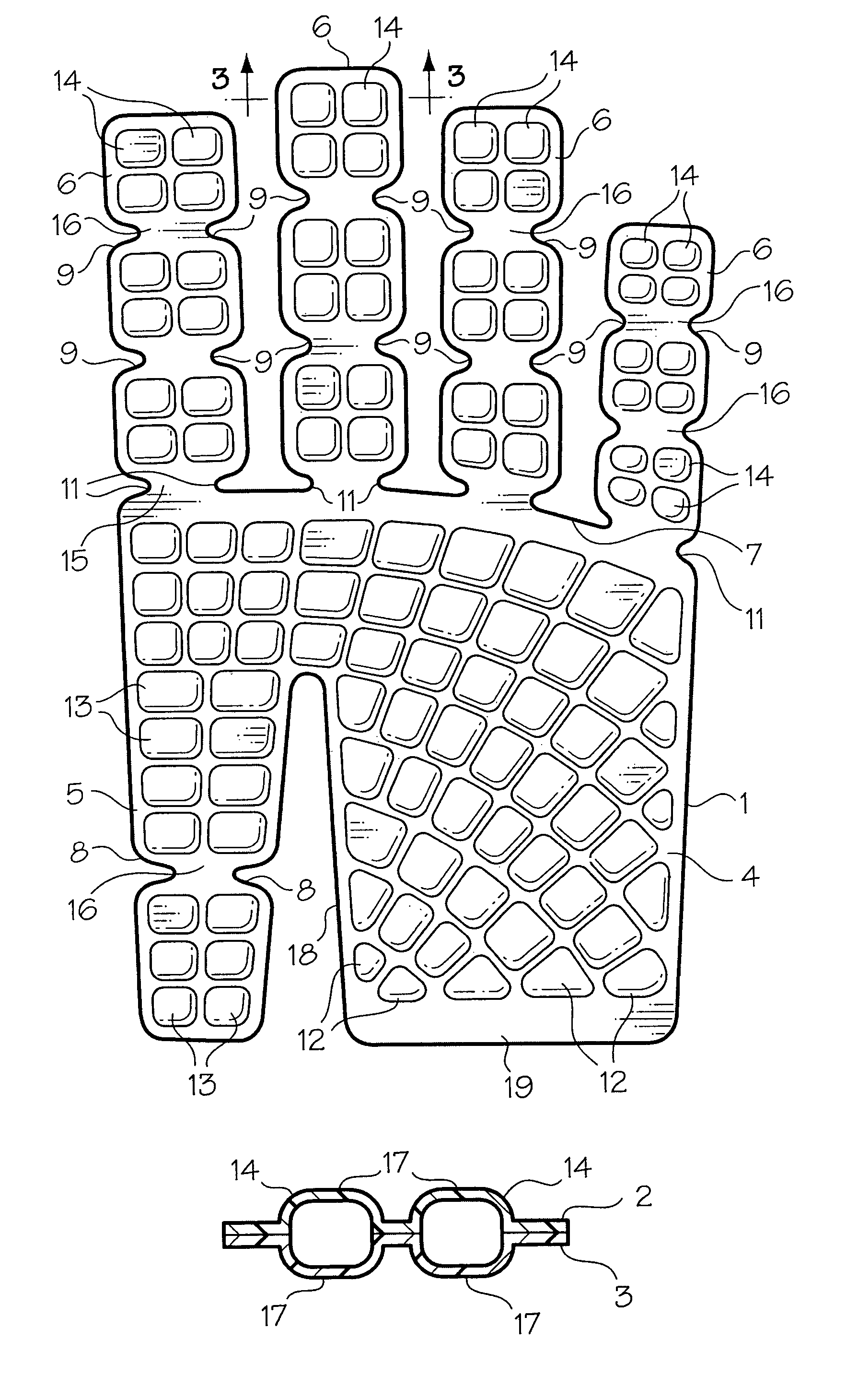
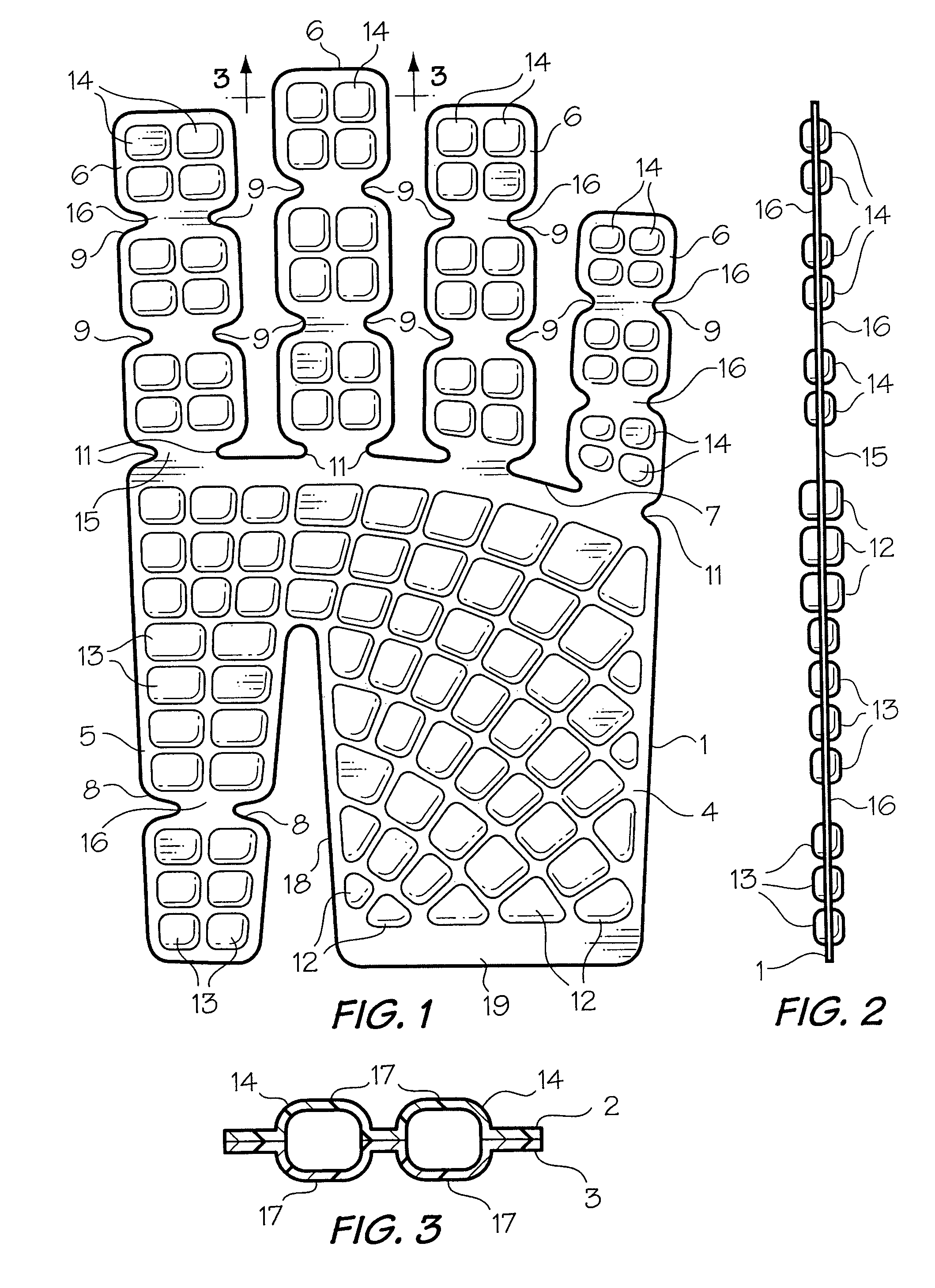
[0011]Referring to the drawing, the damping device of the present invention includes a planar body 1 formed of two layers 2 and 3 (FIG. 3) of 0.8-1.0 mm thick polyurethane film. The two layers 2 and 3 are mirror images of each other and have roughly the shape of a hand including a palm area 4, a thumb area 5 and four finger areas 6. The thumb area 5 extends rearwardly from one end of the palm area 4, and the four finger areas 6 extend forwardly from the opposite end of the palm area. Thus, a single damping device can be used in right and left gloves. The front or finger end 7 of the palm area 5 defines an arc, which curves rearwardly from the index finger side to the little finger side of the body. When placed in a work glove (not shown), the thumb area 5 is attached to the thumb portion of the glove to oppose the index finger. The thumb area 5 and the fingers 6 include opposed notches 8 and 9, respectively for facilitating bending of the damping device in the areas of the thumb and...


PUM


Abstract

A vibration damping device for use in a work glove includes a planar plastic body having palm, thumb and finger areas, and a plurality of resilient, compressible projections extending outwardly from at least one surface of the body. Planar areas or webs in the knuckle and finger joint areas of the body make the device flexible for easy grasping of a tool and bunching of projections in such areas. Bunching of the projections is also avoided or reduced by arranging the projections in parallel, arcuate rows extending from the thumb side rearwardly toward the wrist end of the body.

Description

BACKGROUND OF THE INVENTION[0001]1. Field of the Invention[0002]This invention relates to a vibration damping device, and in particular to vibration damping device for use in a work glove.[0003]2. Discussion of the Prior Art[0004]Vibration damping devices have been used for some time in gloves worn by persons manually operating vibrating tools such as jackhammers and compactors. Examples of such devices are described in U.S. Pat. No. 5,537,688 (Reynolds), U.S. Pat. No. 5,771,490 (Reynolds) and U.S. Pat. No. 6,202,217 (Karall). While such devices are more or less effective in damping vibrations, a problem with existing devices involves flexibility and comfort, particularly in the palm area of the hand. Some devices of the type in question include a plurality of pockets containing air or another compressible fluid. When the pockets are interconnected, during use of a glove containing the bladder, air can be forced out of an area under maximum pressure, thereby reducing the damping eff...

Claims


Application Information

Patent Timeline
Patent Type & Authority Patents(United States)
IPC IPC(8): A41D13/00
CPCA41D19/01523
Inventor AUGER, MICHEL J. G.DOOLITTLE, DOUGLAS C.
Owner IMPACTO PROTECTIVE PRODS
Why Eureka
Try Eureka