Condenser type non-contact manifold ring and power supply device using the same
A non-contact, capacitive technology, used in capacitors, fixed capacitors, and conversion equipment that can be converted to DC without intermediate conversion. It can solve problems such as poor stability, unstable power supply current, and easy damage, and achieve stable The effect of good performance, high reliability and flexible relative movement
- Summary
- Abstract
- Description
- Claims
- Application Information
AI Technical Summary
Problems solved by technology
Method used
Image
Examples
specific Embodiment approach 1
[0014] Embodiment 1: The capacitive non-contact slip ring described in this embodiment is composed of a first capacitor 11 and a second capacitor 12, and the respective first electrode plates and second electrodes of the first capacitor 11 and the second capacitor 12 are The plates can generate relative motion under the premise that the relative distance and relative area remain unchanged. The first electrode 111 of the first capacitor and the first electrode 121 of the second capacitor are fixedly connected together or keep moving synchronously. The second electrode 112 of the capacitor and the second electrode 122 of the second capacitor are fixedly connected together or keep moving synchronously, and both the first capacitor 11 and the second capacitor 12 use air as a dielectric and keep insulation between them.
specific Embodiment approach 2
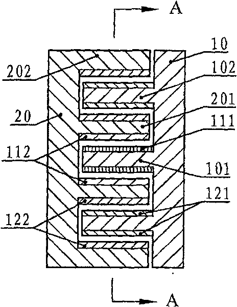
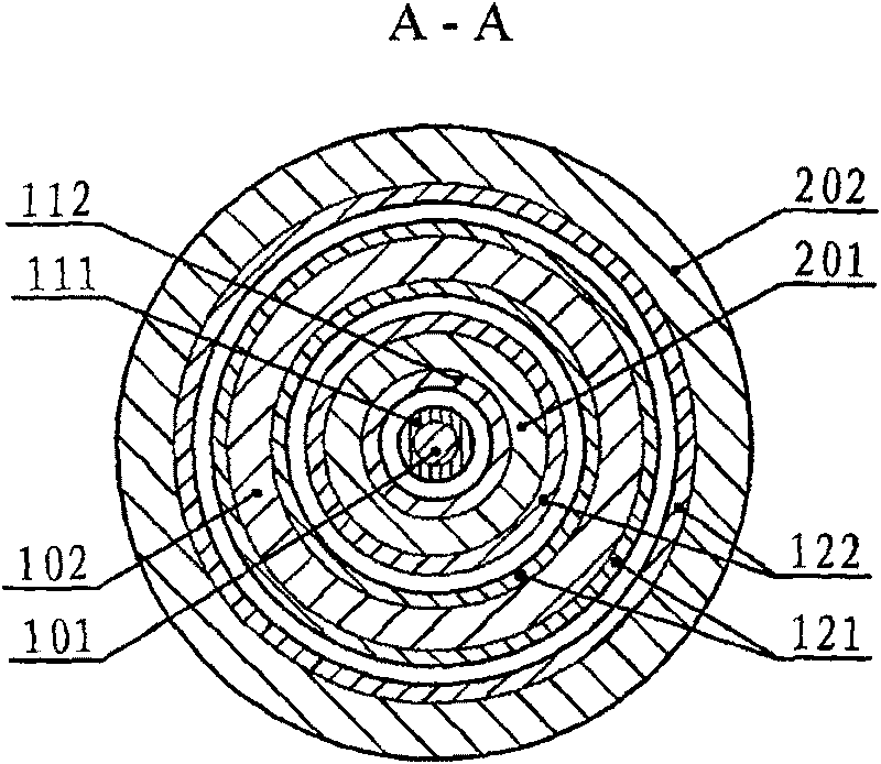
[0015] Specific implementation mode two: see figure 1 , figure 2 This embodiment will be described. The difference between this embodiment and the capacitive non-contact slip ring described in Embodiment 1 is that it also includes a first disk 10 and a second disk 20, and the first disk 10 and the second disk 20 are concentrically opposed to each other. Placed in parallel, and the first disc 10 and the second disc 20 can rotate relatively coaxially; the center of the first disc 10 and the second disc 20 have a raised cylinder 101 on the plane, There is also a protruding ring 102 on the outside of the cylinder 101, on the plane opposite to the first disk 10 of the second disk 20, between the cylinder 101 and the ring 102 on the first disk 10 Corresponding to the raised first ring 201, there is a raised second ring 202 on the outside of the first ring 201, and the second ring 202 is a ring set on the first disc 10 102, between the cylinder 101 and the first ring 201, the fir...
specific Embodiment approach 3
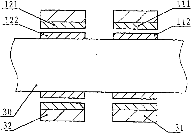
[0017] Specific implementation mode three: see image 3 , Figure 4 This embodiment will be described. The difference between this embodiment and the capacitive non-contact slip ring described in Embodiment 1 is that it also includes a shaft 30, a first collar 31, a second collar 32, and the first collar 31 and the second collar 32 are respectively sleeved on the shaft 30, and are clearance fit with the shaft 30, the first collar 31 and the second collar 32 can rotate relative to the shaft 30 synchronously; the first electrode 111 of the first capacitor is fixed on the first collar 31, the second electrode 112 of the first capacitor is fixed on the side wall corresponding to the first collar 31 on the shaft 30, and the first electrode 121 of the second capacitor is fixed on the inner wall of the second collar 32, The second electrode 122 of the second capacitor is fixed on the side wall of the shaft 30 corresponding to the second collar 32 .
[0018] The capacitive non-cont...
PUM
 Abstract
Description
Claims
Application Information
 - R&D
- Intellectual Property
- Life Sciences
- Materials
- Tech Scout
- Unparalleled Data Quality
- Higher Quality Content
- 60% Fewer Hallucinations
Browse by: Latest US Patents, China's latest patents, Technical Efficacy Thesaurus, Application Domain, Technology Topic, Popular Technical Reports.
© 2025 PatSnap. All rights reserved.Legal|Privacy policy|Modern Slavery Act Transparency Statement|Sitemap|About US| Contact US: help@patsnap.com


