
Filtered shower arm

Active Publication Date: 2011-01-11
FARLEY DAVID K
View PDF16 Cites 55 Cited by
  • Summary
  • Abstract
  • Description
  • Claims
  • Application Information

AI Technical Summary

Benefits of technology

[0009]Accordingly, it is a general object of the present invention to provide an improved shower filter assembly. It is a more particular object of the present invention to provide a combination shower arm and water filter. It is a further object of the present invention to provide a compact combination shower arm and water filter that takes up a minimum of space. It is yet another object of the present invention to provide a compact combination shower arm and water filter that replaces an existing shower arm and, if used, a shower filter. It is a still further object of the present invention to provide a combination shower arm and water filter that may be used with a separate or integrally formed showerhead. It is yet a s

Problems solved by technology

However, because of the size of the filter and the attached showerhead, and / or the filtered showerhead, they may extend too far into the shower area.
Furthermore, the known filters and / or filtered showerheads add weight to the shower arm, which over time may cause problems.
Such known filters and filtered showerheads also tend to be costly to manufacture and are not used by some persons because of their size or style.
For example, the known filters and filtered showerheads do not always match person's aesthetic taste, and / or the overall décor of a bathroom or shower area.
Finally, the known filters and filtered showerheads cannot be used with large, modern showerheads, such as the flower shaped or watering can type, and do not have an integrated feel or look when used with known shower arms.
While the foregoing prior art devices provide improved filtration of hot water passing through them, they do not provide for a filtered shower arm that may be attached or secured between a water line behind a shower wall and a showerhead that reduces cost and weight.

Method used


Image

  • Filtered shower arm
  • Filtered shower arm
  • Filtered shower arm

Examples


first embodiment

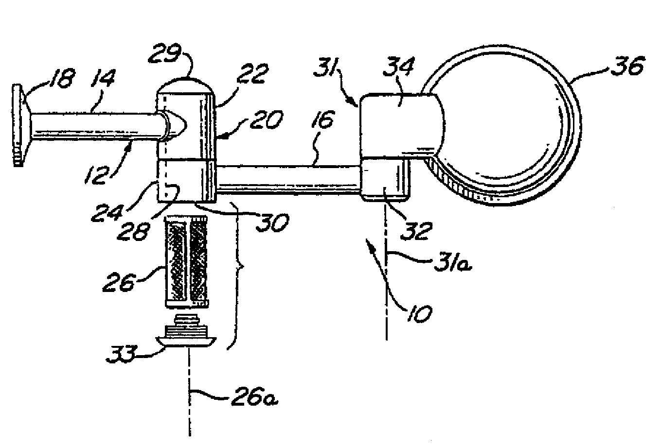
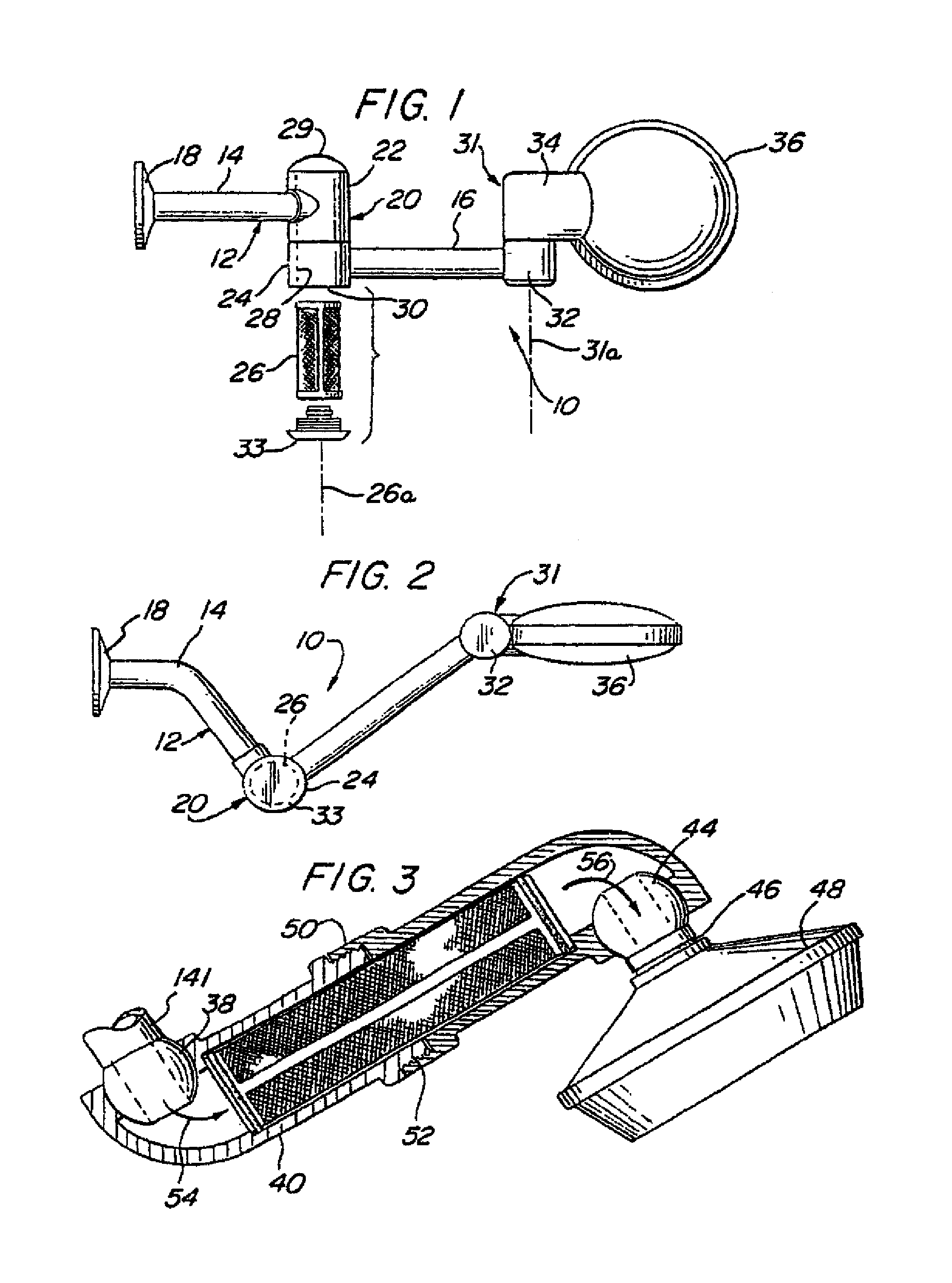
[0025]Turning now to the drawings, FIGS. 1 and 2 illustrate a combined shower arm and filter assembly 10 of the present invention. The combined shower arm and filter assembly 10 has a multi-component or multi-piece body or housing 12 which is used to replace the normal shower arm coming out of a shower wall, not shown.

[0026]As shown, the body 12 includes a first hollow arm 14 and a hollow second arm 16 that acts as an extension of the first arm. A wall cover 18 is shown on arm 14 at an inlet, which inlet has a threaded end, not shown, for connection to a plumbing connection in or behind a shower wall, not shown. The arms 14, 16 are movably held together in any desired manner, as by means of a holding portion or joint 20, comprising movable portions 22, 24 that allow the arms 14, 16 to move or rotate with respect to each other. The movable portions 22, 24 are preferably formed transverse or at a 90° angle to the arms 14, 16, when looking at the drawings. A water filter assembly or el...

second embodiment

[0030]a device 37 is shown in FIG. 3. The device 37 has an arm 141 that may include a ball, swivel or other movable joint 38 connected to an arm 40 having a water filter assembly or element 42 held therein. A further ball, swivel or other movable joint 44 is connected to arm 40, after filter 42. The movable joint 44 includes an outer end 46 having a showerhead 48 formed integrally therewith, or removably mounted thereto, as by means of a threaded end. The arm 40 is comprised of two portions connected or coupled together, for example, by externally threaded portions 50, 52, to enable the filter 42 to be easily removed for reversal or replacement.

[0031]In use, when the device 37 is properly mounted in a shower, water enters the inlet end of hollow arm 141 and flows in the direction of arrow 54 to the hollow internal portion of arm 40, axially through the filter 42 held in the arm 42, and then in the direction of arrow 56 through the ball or swivel joint 44 and out through the showerhe...

seventh embodiment

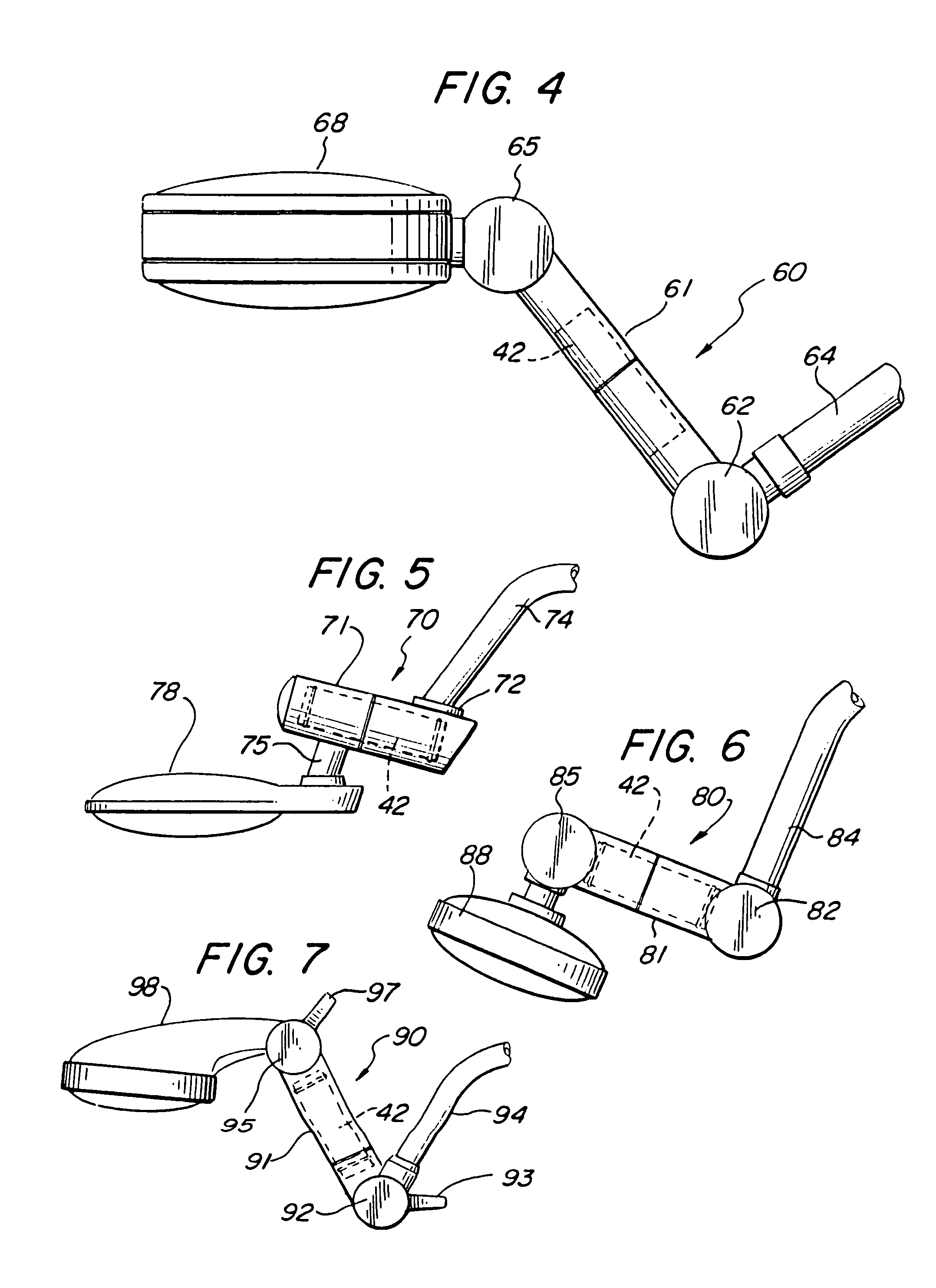
[0034]Turning now to FIGS. 8 and 9, there shown is a combined shower arm and filter assembly 100 of the present invention. The combined shower arm and filter assembly 100 has a multi-piece body or housing 102 which is used to replace the normal shower arm coming out of a shower wall, not shown. The body 102 includes a first hollow arm 104 and a second hollow arm 106. A wall cover 108 is shown on arm 104 at an inlet, which inlet has a threaded end, not shown, for connection to a plumbing connection in or behind a shower wall. The arms 104, 106 are movably held together in any desired manner, as by means of a holding portion or joint 110, comprising hollow movable portions 112, 114. The hollow movable portions 112, 114 allow the arms 104, 106 to move or rotate with respect to each other. The movable portions 112, 114 of the holding portion or joint 110 are preferably formed transversely to or at a 90° angle to the arms 104, 106. A filter holding portion 111 having a filter element 26 ...


PUM


Abstract

A combination shower arm and water filter having an integrated design for attachment between a water pipe behind a shower wall and a showerhead. The combination shower arm and water filter including a body having a first hollow arm and a second hollow arm connected to a central cartridge holding portion. The filter holding portion has a central opening with a filter cartridge or element removably held in a hollow chamber formed above the filter holding portion by means of a cap that is removably secured to the an upwardly extending annular portion formed on the filter holding portion. Water entering the combined shower arm and filter assembly through the first hollow arm is directed into the hollow chamber for passage through filter media in the filter cartridge or element before it exits through the second hollow arm and out a showerhead.

Description

CROSS-REFERENCE TO RELATED APPLICATION[0001]This application is a Continuation-in-Part of application Ser. No. 10 / 461,104, entitled FILTERED SHOWER ARM, filed Jun. 13, 2003 now U.S. Pat. No. 7,097,122.BACKGROUND OF THE INVENTION[0002]1. Field of the Invention[0003]This invention generally relates to filtered shower arms and, more particularly, to a combination shower arm and water filter that is connected directly to a water pipe behind a shower wall to provide a more compact and attractive device that improves showering.[0004]2. Description of the Prior Art[0005]Shower filters for use in conjunction with showerheads and filtered showerheads in showers are known. For example, filters are inserted at ends of shower arms, with showerheads then secured to the filters, or filtered shower heads are attached directly to the ends of shower arms. However, because of the size of the filter and the attached showerhead, and / or the filtered showerhead, they may extend too far into the shower ar...

Claims


Application Information

Patent Timeline
IPC IPC(8): B05B1/14B05B15/08B05B1/30B01D27/00B05B15/68
CPCB05B15/008B05B15/066E03C1/0409E03C1/06E03C1/066B05B1/18E03C2201/40B05B15/652B05B15/40
Inventor FARLEY, DAVID K.
Owner FARLEY DAVID K
Learn More