
Video encoder and method for detecting and encoding noise

a video encoder and encoder technology, applied in the field of video compression, can solve the problems of temporal noise appearing on the tv screen, noise presented to the input of the encoder, and the encoder's encoding steps are not rigidly defined, so as to prevent buffer overflow, reduce the peak bit rate, and prevent the halting of encoder hardware

Inactive Publication Date: 2011-01-11
AVAGO TECH WIRELESS IP SINGAPORE PTE
View PDF29 Cites 7 Cited by
  • Summary
  • Abstract
  • Description
  • Claims
  • Application Information

AI Technical Summary

Benefits of technology

Thus, the system and method of the present invention advantageously handle and encode noise as soon as possible and enable the invention to reduce the peak bit rate to prevent buffer overflows and to prevent encoder hardware from halting. The present invention also advantageously detects noise within one frame of time during a single pass.

Problems solved by technology

Due to limitations in digital signal storage capacity and limitations in network and broadcast bandwidth, compression of digital video signals is essential to digital video storage and transmission.
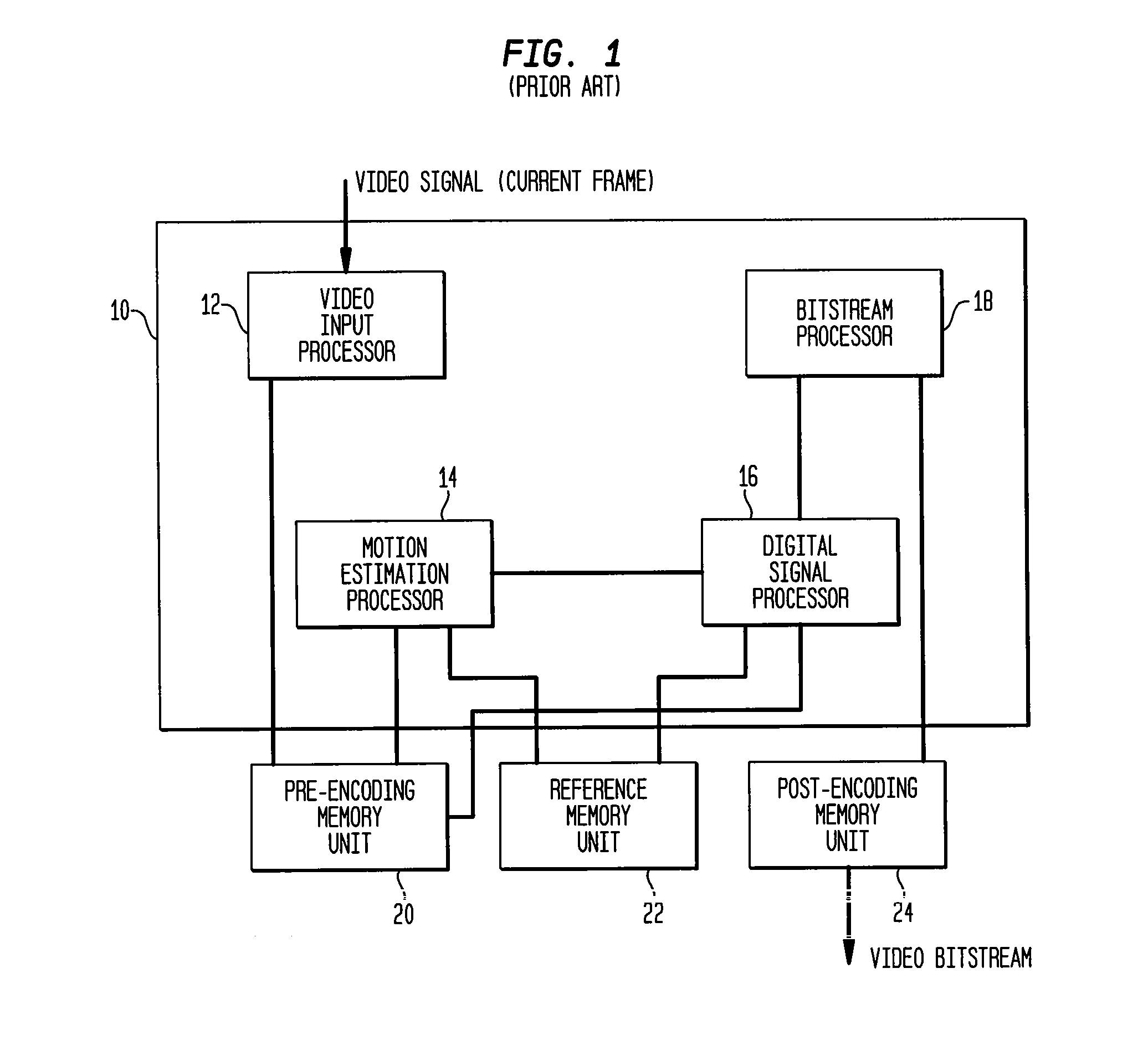
In other words, encoding steps are not rigidly defined allowing tradeoffs between video quality, compression ratio, and compute power of the encoder.
During operation of an encoder, it is inevitable that some noise is presented to the input of the encoder.
For example, when a TV is used as a source for the encoder, a temporal noise appears on the TV screen when the TV channel is switched.
A very high or peak bit rate causes the output buffer to overflow which in turn causes the encoder to stop functioning.
However, the problem with this solution is that there are many video sources with high frequencies.
Eliminating high frequencies of certain video sources reduces image quality.
It is not possible to analyze the whole frame before encoding it.

Method used


Image

  • Video encoder and method for detecting and encoding noise
  • Video encoder and method for detecting and encoding noise
  • Video encoder and method for detecting and encoding noise

Examples


Embodiment Construction

The present invention will now be described in detail with reference to a few preferred embodiments thereof as illustrated in the accompanying drawings. In the following description, numerous specific details are set forth in order to provide a thorough understanding of the present invention. It will be apparent, however, to one skilled in the art, that the present invention may be practiced without some or all of these specific details. In other instances, well known processes or steps have not been described in detail in order not to unnecessarily obscure the present invention.

Embodiments of the invention are discussed below with references to FIGS. 2 to 7. However, those skilled in the art will readily appreciate that the detailed description given herein with respect to these figures is for explanatory purposes as the invention extends beyond these limited embodiments.

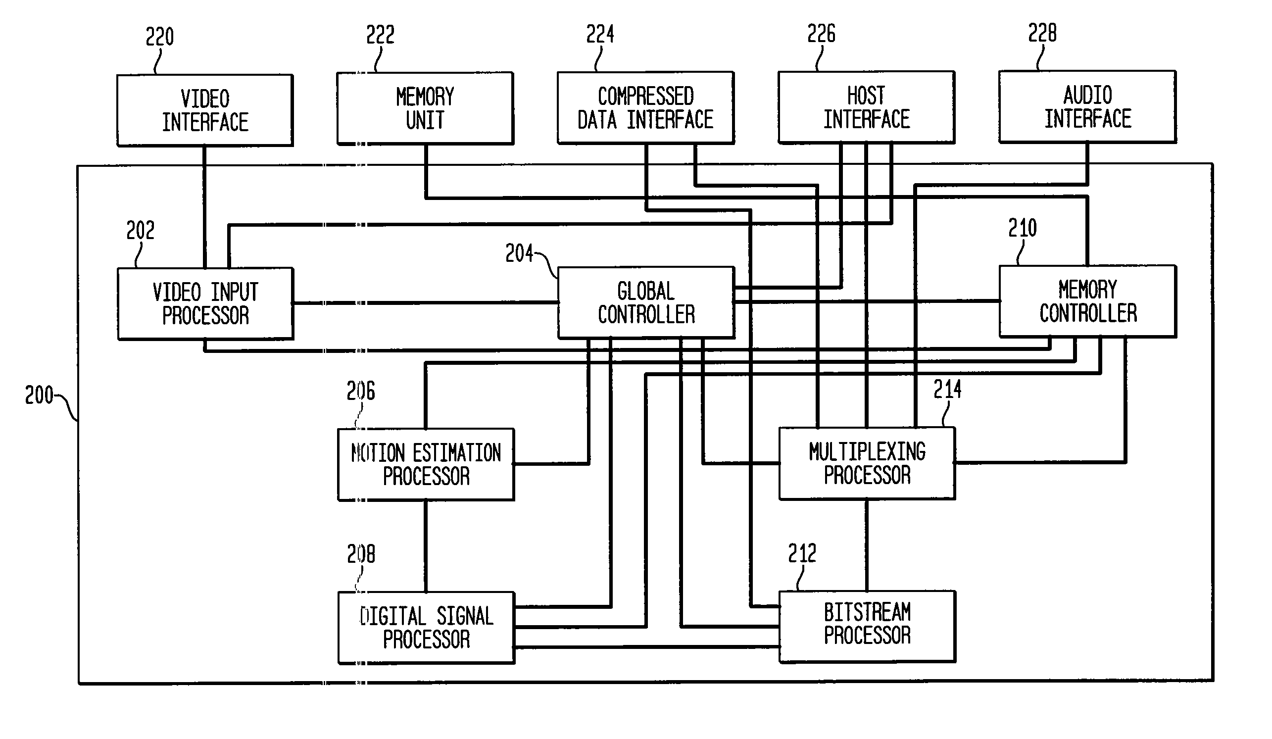
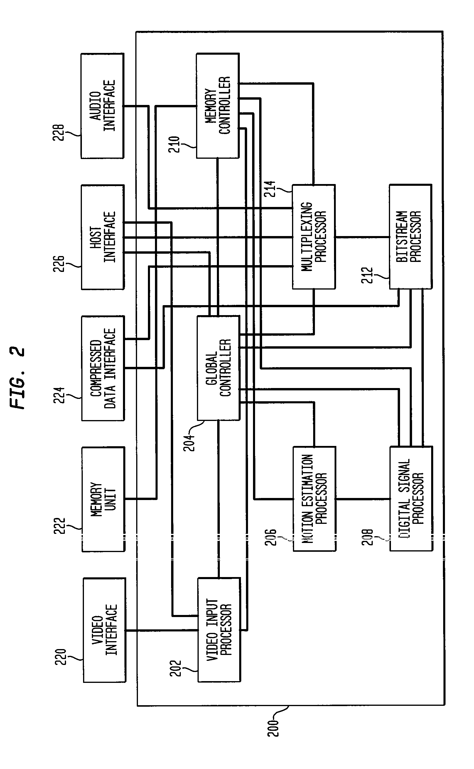
Referring now to FIG. 2, there is shown a block diagram of one embodiment of a video encoding system 200 constru...


PUM


Abstract

A digital video signal encoder and method for detecting and encoding noise is disclosed. In a frame in a video signal, the variance of at least four macroblock luminance blocks is calculated. The Log2 of the minimum of these variances is determined. A running sum of the Log2 calculations is calculated and compared to a noise threshold to determine whether or not the frame contains noise. In one embodiment, a frame is determined to contain noise if the running sum is greater than a noise threshold and encodes the remaining portion of the frame as noise. In another embodiment, a current frame is determined to contain noise and is encoded as noise if the previous frame contained noise. The present invention may encode noise by overriding the original bit rate quantiser scale and / or removing at least one high frequency from a noise block using a DCT filter.

Description

BACKGROUND OF THE INVENTION1. Field of the InventionThe present invention relates generally to video compression, and more specifically to a digital video encoder system and method for detecting and encoding noise.2. Related ArtDigital video products and services and devices for storage and retrieval of video streams on the Internet are ubiquitous in the marketplace. Due to limitations in digital signal storage capacity and limitations in network and broadcast bandwidth, compression of digital video signals is essential to digital video storage and transmission. As a result, many standards for compression and encoding of digital video signals have been promulgated. These standards specify with particularity the form of encoded digital video signals and how such signals are to be decoded for presentation to a viewer.One example of such a standard is the ISO / IEC international Standard 13818 (generally referred to as MPEG-2 format) created by the Moving Picture Experts Group (MPEG) and...

Claims


Application Information

Patent Timeline
Patent Type & Authority Patents(United States)
IPC IPC(8): H04N7/12H04N11/02G06T9/00H04N7/26H04N7/50
CPCH04N19/176H04N19/61H04N19/117H04N19/18H04N19/132H04N19/14H04N19/126
Inventor YANKILEVICH, ITZIK
Owner AVAGO TECH WIRELESS IP SINGAPORE PTE
Learn More