Image forming apparatus including a holding portion having an air vent

Active Publication Date: 2011-01-11
BROTHER KOGYO KK
View PDF11 Cites 3 Cited by
  • Summary
  • Abstract
  • Description
  • Claims
  • Application Information

AI Technical Summary

Benefits of technology

According to the image forming apparatus of the present invention, cooling air may be efficiently guided to width-direction end por

Problems solved by technology

It is, however, difficult to efficiently cool the heat generating components disposed in width

Method used


Image

  • Image forming apparatus including a holding portion having an air vent
  • Image forming apparatus including a holding portion having an air vent
  • Image forming apparatus including a holding portion having an air vent

Examples


first embodiment

1. Configuration of Laser Printer

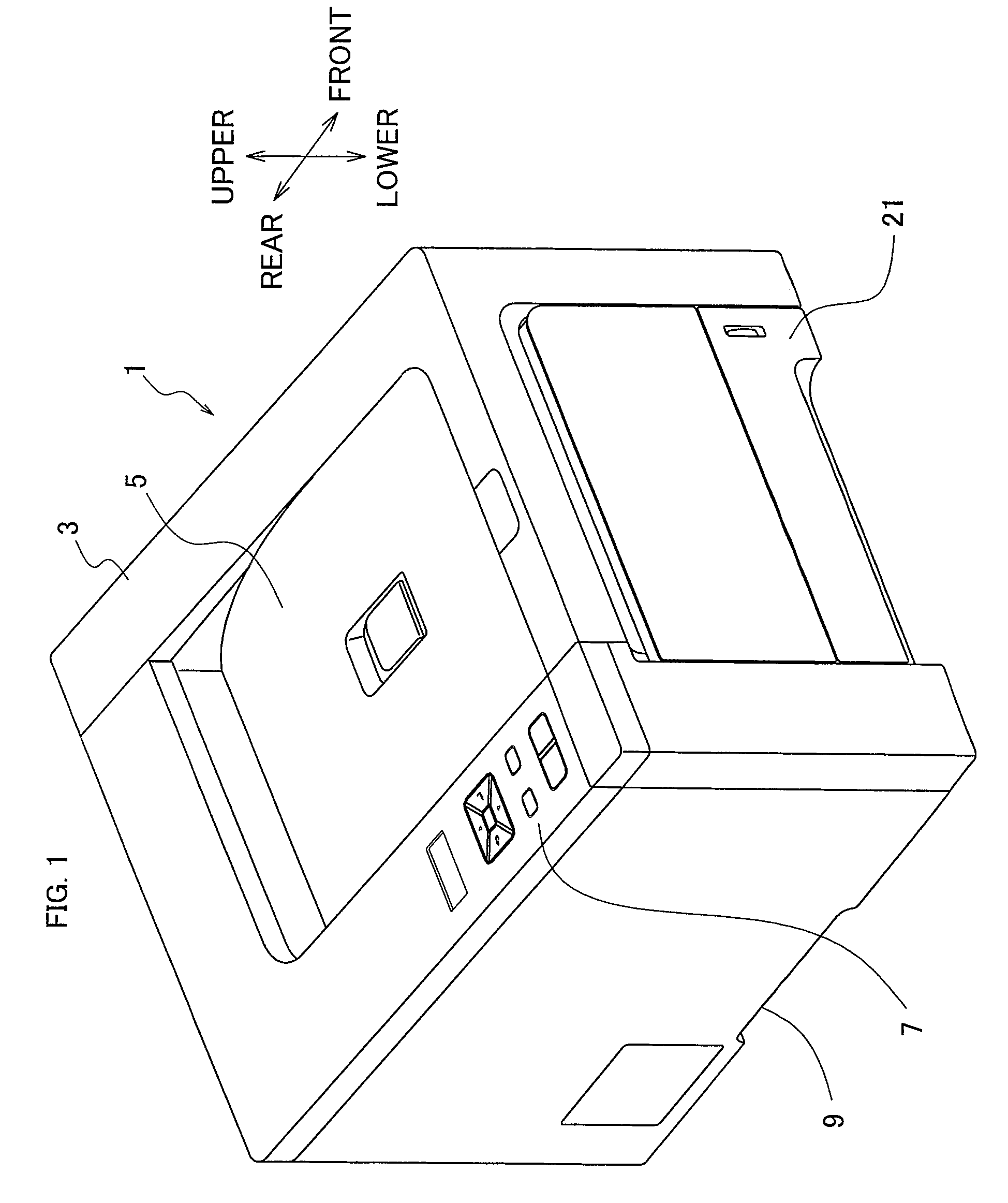
A laser printer 1 of a first embodiment is placed with an upper direction of FIG. 1 as an upper direction of the gravity direction, and usually is used with a right side of FIG. 1 as a front side.

As shown in FIG. 1, a housing 3 of the laser printer 1 having a substantially box-like shape (a cubic shape) covers a frame 100 (see FIG. 5) and constitutes an exterior design.

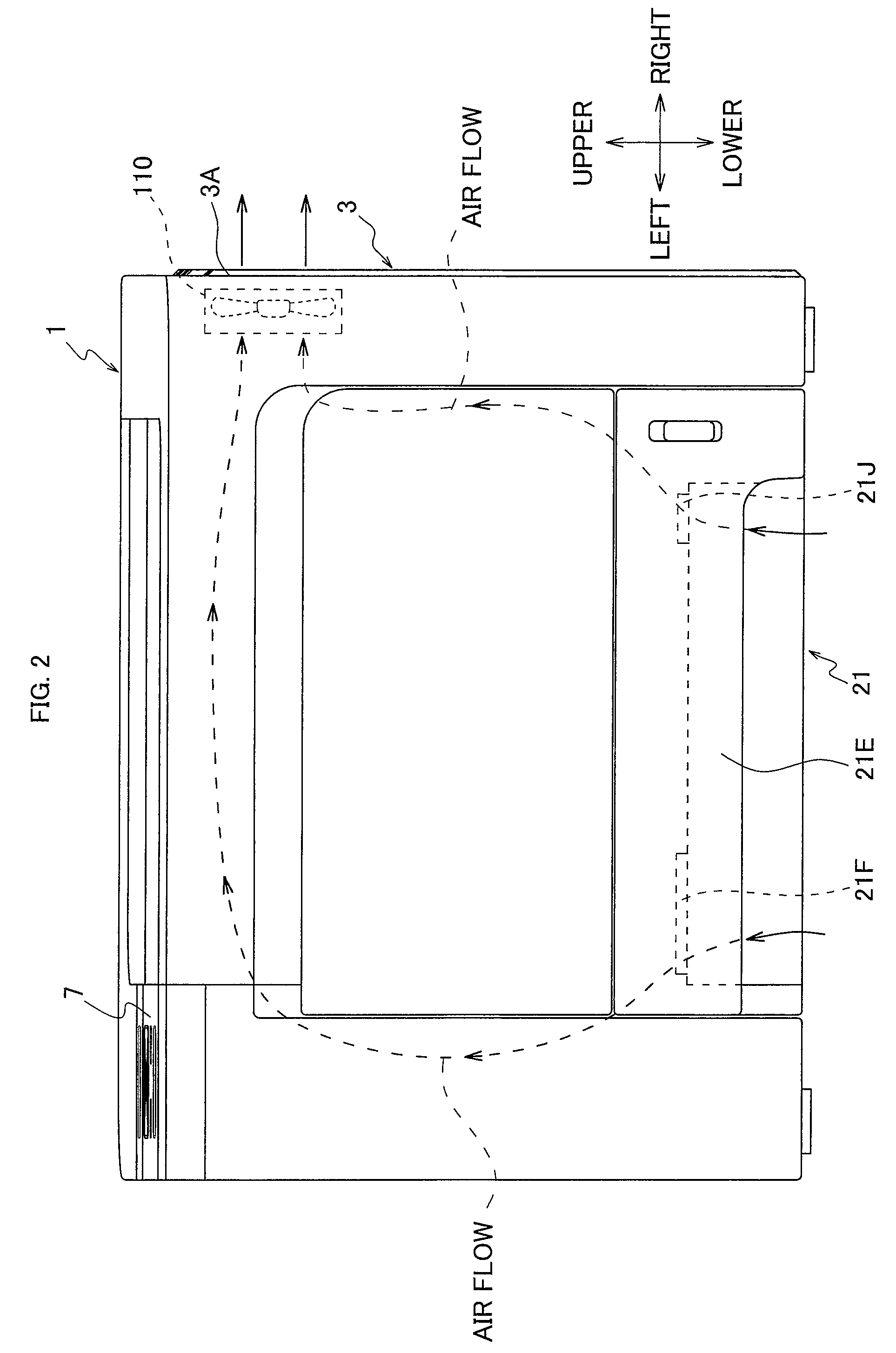
In an upper side of the housing 3, a paper discharge tray 5, an operation panel 7 and others are provided. A recording medium, such as a sheet of paper or an OHP sheet (hereinafter simply referred to as a “sheet”), discharged from the housing 3 after printing is placed on the paper discharge tray 5. The operation panel 7 is used to perform settings on the laser printer 1. In a lower lateral side of the housing 3, a holding section 9 for lifting the laser printer 1 is provided.

Also, as shown in FIG. 6, an image forming portion 10, a feeder portion 20, a conveyance mechanism 30, and othe...

second embodiment

Since a laser printer in a second embodiment is configured substantially the same as the image forming apparatus in the first embodiment shown in FIGS. 1-8, only differences from the first embodiment will be described below.

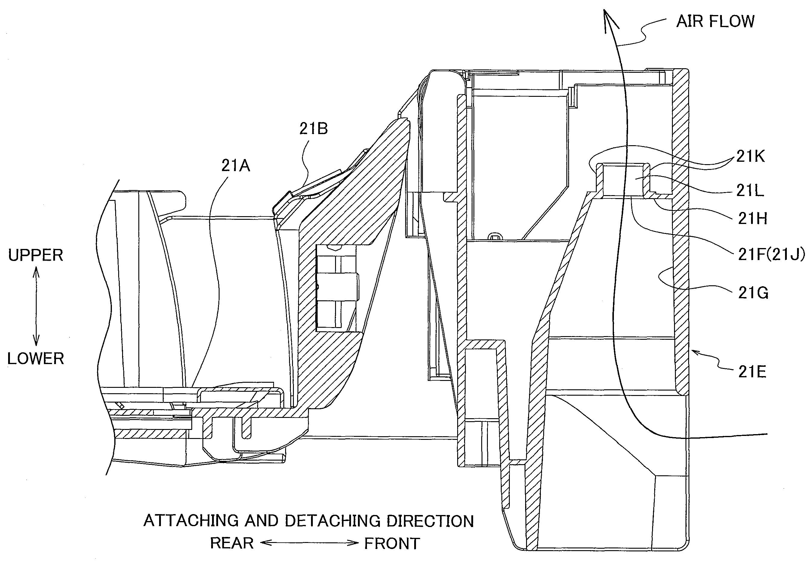
In the first embodiment, the decrease in the mechanical strength of the holding portion 21E is suppressed by providing the bridge portions 21L to the air vents 21J and 21F.

In the second embodiment, as shown in FIG. 9, each of the air vents 21J and 21F is constituted by a plurality of air vent holes 21M aligned in a horizontal direction perpendicular to the attaching and detaching direction (i.e., in the width direction of the paper feed tray 21). Accordingly, portions between respective neighboring air vent holes 21M function as reinforcing members for the holding portion 21E in the present embodiment. Thus, a decrease in the mechanical strength of the holding portion 21E by providing the air vents 21J and 21F may be reduced. Also, a wall portion 21P, which is pr...


PUM


Abstract

An image forming apparatus includes a placement tray on which a recording medium is placed and which is attachably and detachably assembled into a housing. The placement tray includes a holding portion having an upwardly concave configuration at one end of the placement tray in an attaching and detaching direction of the placement tray. The holding portion includes at least one air vent for taking air into the housing in a vicinity of at least one of both end portions of the holding portion in a width direction perpendicular to the attaching and detaching direction.

Description

CROSS-REFERENCE TO RELATED APPLICATIONSThis application claims the benefit of Japanese Patent Application No. 2006-194167 filed Jul. 14, 2006 in the Japan Patent Office, the disclosure of which is incorporated herein by reference.BACKGROUNDThe present invention relates to an image forming apparatus, and particularly to an image forming apparatus of an electrophotographic type, such as a laser printer, a copying machine or the like.A housing of a typical image forming apparatus houses heat generating components, such as a power board and an electric motor. In order to maintain such heat generating components at temperatures lower than respective upper temperature limits, an air vent for taking in cooling air is provided in a holding portion of a paper feed tray which is attachably and detachably assembled into the housing (an image forming apparatus main body) according to a known technique.The holding portion is a handle portion which a user holds when the user manually attaches or ...

Claims


Application Information

Patent Timeline
IPC IPC(8): G03G21/20
CPCB41J29/02G03G15/6502G03G21/206G03G2215/00383G03G2221/1645
Inventor UKAI, MASAMITSU
Owner BROTHER KOGYO KK
Why Eureka
Try Eureka