A Device For Automatically Connecting A Vehicle To An Electric Power Supply

Active Publication Date: 2016-01-14
IPALCO BV
View PDF9 Cites 11 Cited by
  • Summary
  • Abstract
  • Description
  • Claims
  • Application Information

AI Technical Summary

Benefits of technology

[0036]The protection cover is advantageously formed by two opposing half-covers, pivotable about two parallel, substantially horizontal axes located on two opposite sides of the second connector part, one half-cover partially overlapping the other half-cover. It will be appreciated that using two opposing half-covers ensures a better splashed water and contact protection than would a single cover.
[0037]According to a further aspect of the invention, the upper part of the guide block forms at least one curved guide surface for guiding the power cable when a horizontal force component is exerted on the power cable; and the second guiding device and the second connector part are mounted in a casing which advantageously forms at its outlet a fixed curved guide surface in extension of the curved guide surface formed by the upper part the guide block. Working with a curved guide surface formed partially by the guide block and partially by a casing containing the second guiding device ensures a very efficient guiding of the power cable form a substantially vertical direction at the outlet of the first connecto

Problems solved by technology

A major disadvantage of RMG cranes is that for servicing two container stacking areas not located along the same rail track, two different RMG cranes are required, because the RMG crane cannot travel from a first rail track onto a second rail track.
However, as an RTG crane must be capable of moving between two distant container stacking areas, they can no longer be powered by a fixed connection to electric power mains.
However, environmental and maintenance issues, as well as strongly increasing diesel prices are making onboard diesel engines less and less attractive.
It will however be noted that the collector trolley and/or the conductor rails are easily damaged, and that the collector rails present moreover a high risk of electrocution.
It will be appreciated that manually disconnecting the plug of the power cable from the socket in the joint-box of the first cable trench and manually reconnecting it to the socket of the joint-box of the second cable trench, are time consuming, burdensome and potentially dangerous.
They are time consuming, because the crane operator must leave his control cabin, which is normally fixed to a tro

Method used


Image

  • A Device For Automatically Connecting A Vehicle To An Electric Power Supply
  • A Device For Automatically Connecting A Vehicle To An Electric Power Supply
  • A Device For Automatically Connecting A Vehicle To An Electric Power Supply

Examples


Embodiment Construction

[0069]It will be understood that the following description and the drawings to which it refers describe by way of example embodiments of the claimed subject matter for illustration purposes. They shall not limit the scope, nature or spirit of the claimed subject matter.

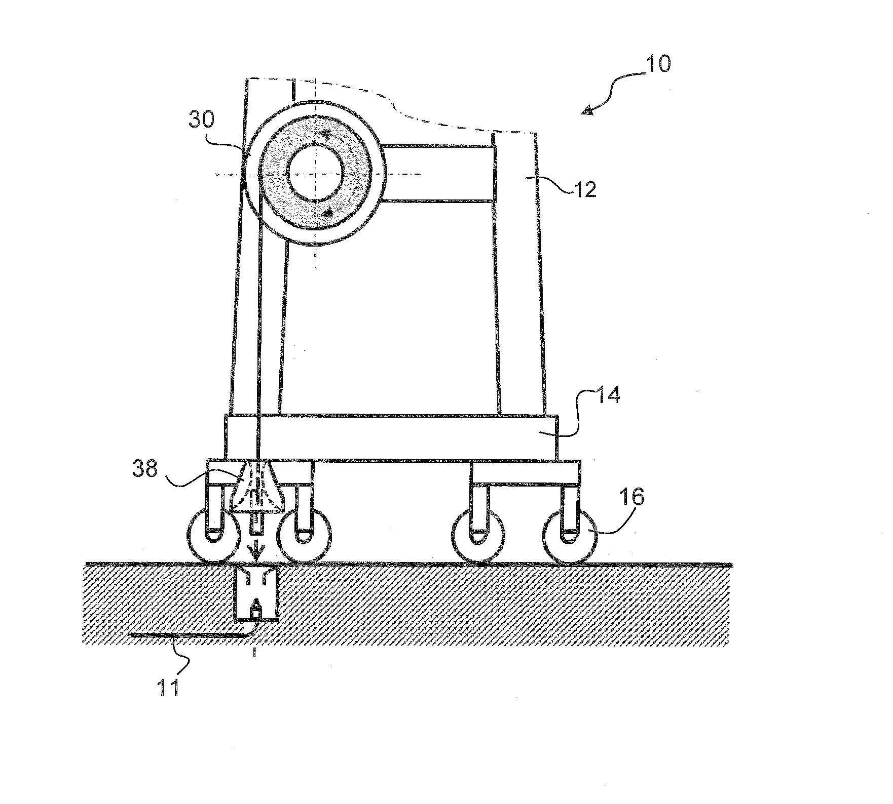
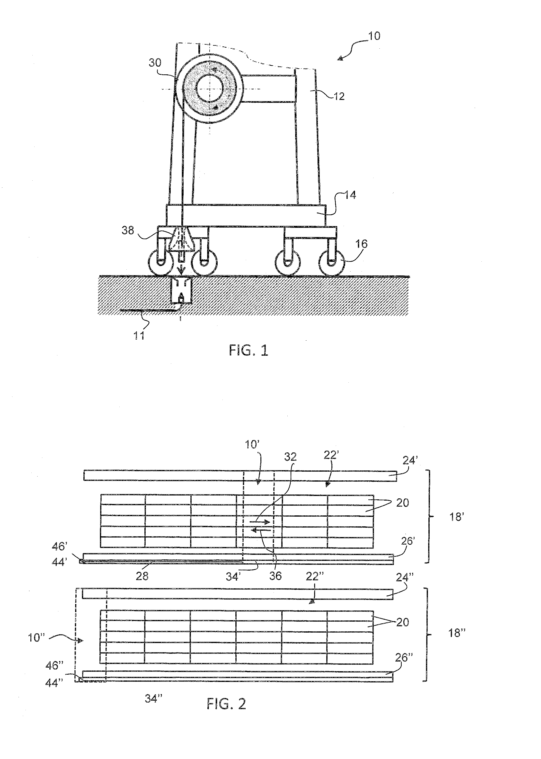
[0070]FIG. 1 schematically shows as a rubber tired gantry (RTG) crane 10 as a general illustration of a vehicle that can be connected to a fixed electric power supply line 11 by means of a device in accordance with the present invention. The RTG crane 10 comprises a frame bridge 12, which supports hoisting equipment (not shown in the drawing). The frame bridge 12 is supported itself by a mobile platform 14, with wheels equipped with rubber tires 16 (i.e. the crane may travel on any flat surface and is not bound to a railway line).

[0071]As illustrated in FIG. 2, the RTG crane (here schematically represented by a dashed rectangle 10′ in a first position and a dashed rectangle 10″ in a second position) is conceived more ...


PUM


Abstract

A device for automatically connecting a vehicle to an electric power supply, comprises: a turn-over-anchor (48, 210), including a first connect- or part (42, 216) connected to the cable (28, 208); and a docking station (50, 212), including a second connector part (44, 230) configured for mating with the first connector part (42, 216) according to a vertical coupling axis (47, 236), when the turn-over-anchor (48, 210) is vertically deposited into the docking station (50, 212). The device further includes two horizontally spaced vertical rods (58′, 58″, 246′, 246″), each of which is arranged so as to vertically penetrate into a guide opening or hole (62′, 62″, 248′, 248″) of an opposite element (50′, 50″), when the turn-over-anchor (48, 210) is deposited into the docking station (50, 212), and is dimensioned so as to be self-locking in the hole (62′, 62″, 248′, 248″), if the turn-over-anchor (48, 210) is subjected to a significant force that is not aligned with the vertical coupling axis (47, 236).

Description

TECHNICAL FIELD[0001]The present invention generally relates to a device for automatically connecting a vehicle to an electric power supply. It relates more particularly to a device for automatically connecting a mobile gantry crane to an electric power supply.BACKGROUND ART[0002]In container yards, mobile gantry cranes are used for lifting, moving and stacking freight containers.[0003]A first type of such a gantry crane moves with steel wheels on a rail track, which consists of two rails bordering a substantially rectangular container stacking area lengthwise. These first gantry cranes are referred to as rail-mounted gantry cranes (RMG cranes). RMG cranes are generally electrically powered via a power cable wound on a cable reel or winch mounted on one side of the gantry crane. To avoid damaging the power cable, the latter is—during movement of the RMG along its rail track—placed in a trench extending along one of the rails of the rail track, plumb-vertically under the horizontal t...

Claims


Application Information

Patent Timeline
IPC IPC(8): B66C13/12H01H9/54H01R13/62H02G11/02
CPCB66C13/12H01R13/6205H01H9/54H02G11/02B66C19/007Y02T10/7072Y02T10/70
Inventor TERUZZI, SANDRO
Owner IPALCO BV
Why Eureka
Try Eureka