Orthopedic brace of knee joint

a knee joint and orthopaedic technology, applied in the field of orthopaedic braces of knee joints, can solve the problems that the joint movement and walking of the wearer cannot be smoothly performed, and achieve the effects of smooth joint movement and walking, efficient induced and guided, and specific connection pressur

Inactive Publication Date: 2009-07-16
DAVINCIMEDITEC
View PDF2 Cites 21 Cited by
  • Summary
  • Abstract
  • Description
  • Claims
  • Application Information

AI Technical Summary

Benefits of technology

[0018]As described above, according to the present invention, the linear slit and the curved slit of the second link are separately formed such that moving paths of the linear movement and the rotation do not intersect or overlap each other and are also connectedly extended such that the linear movement and the rotation induce each other. Accordingly, the linear movement and the curved movement of the upper support member, intersecting each other, can be efficiently induced and guided while the upper support member moves in connection with the first link with respect to the lower support member.
[0019]Thus, in knee joint restoration for a bowlegged or knock-kneed patient, when the hinge assembly having the second link is installed at an inside portion or an outside portion of knee bones having a small distance therebetween, the upper support member linearly moves in a direction away from the lower support member while interlocking with the forward rotation of the upper support member. As a result, the hinge assembly can correct a bent joint of the wearer to enable smooth joint movement and walking.
[0020]Further, in knee joint restoration for a bowlegged or knock-kneed patient, when the hinge assembly having the lower plate spring and the upper plate spring is installed at an outside portion or an inside portion of knee bones having an extended distance therebetween, the lower leaf spring and the upper leaf spring are elastically deformed. Accordingly, even though the hinge assembly is used for a patient having a large knee joint due to excessive deformation of knee bones, a specific connection pressure can be maintained without excessively pressing the knee.
[0021]Further, when the lower sponge having a size increasing from bottom to top and the upper sponge having a size increasing from top to bottom are respectively attached to the lower support member and the upper support member, a simple structure of a single support member can be manufactured instead of a conventional structure of double support members with a leaf spring coupled therebetween. Further, it is possible to improve adhesion between the lower and upper support members and the skin of the wearer and wearing comfort of the brace. Since the sponge can be deformed flexibly and elastically by a pressing force between the skin of the wearer and the support member, the upper support member can move more smoothly.

Problems solved by technology

Accordingly, moving paths of the linear movement and the rotation intersect each other and frequently disturb each other, thereby causing a problem that joint movement and walking of the wearer cannot be smoothly performed.

Method used


Image

  • Orthopedic brace of knee joint
  • Orthopedic brace of knee joint
  • Orthopedic brace of knee joint

Examples


first embodiment

[0036]First, the orthopedic brace of a knee joint according to the present invention will be described in detail with reference to the accompanying drawings.

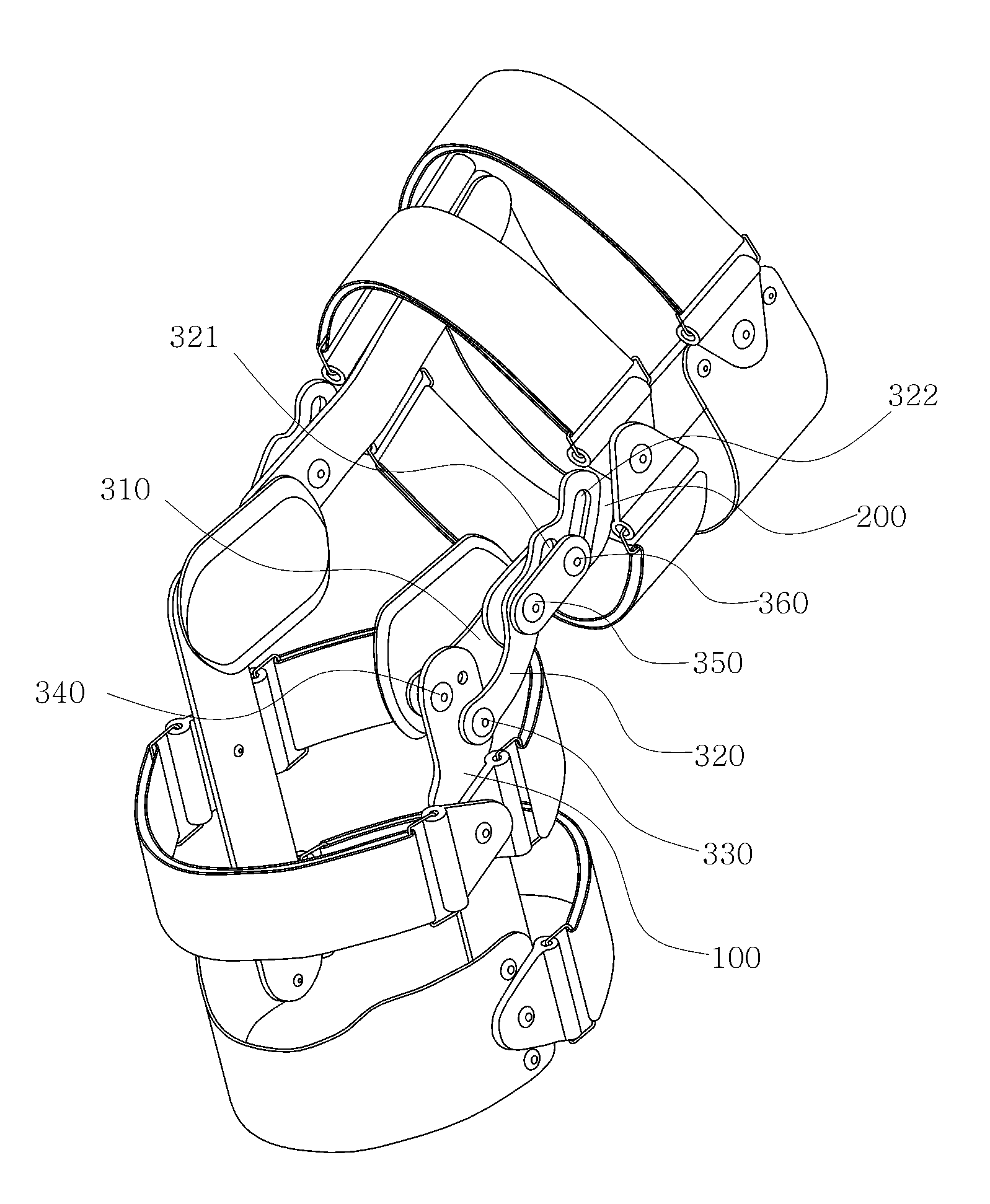
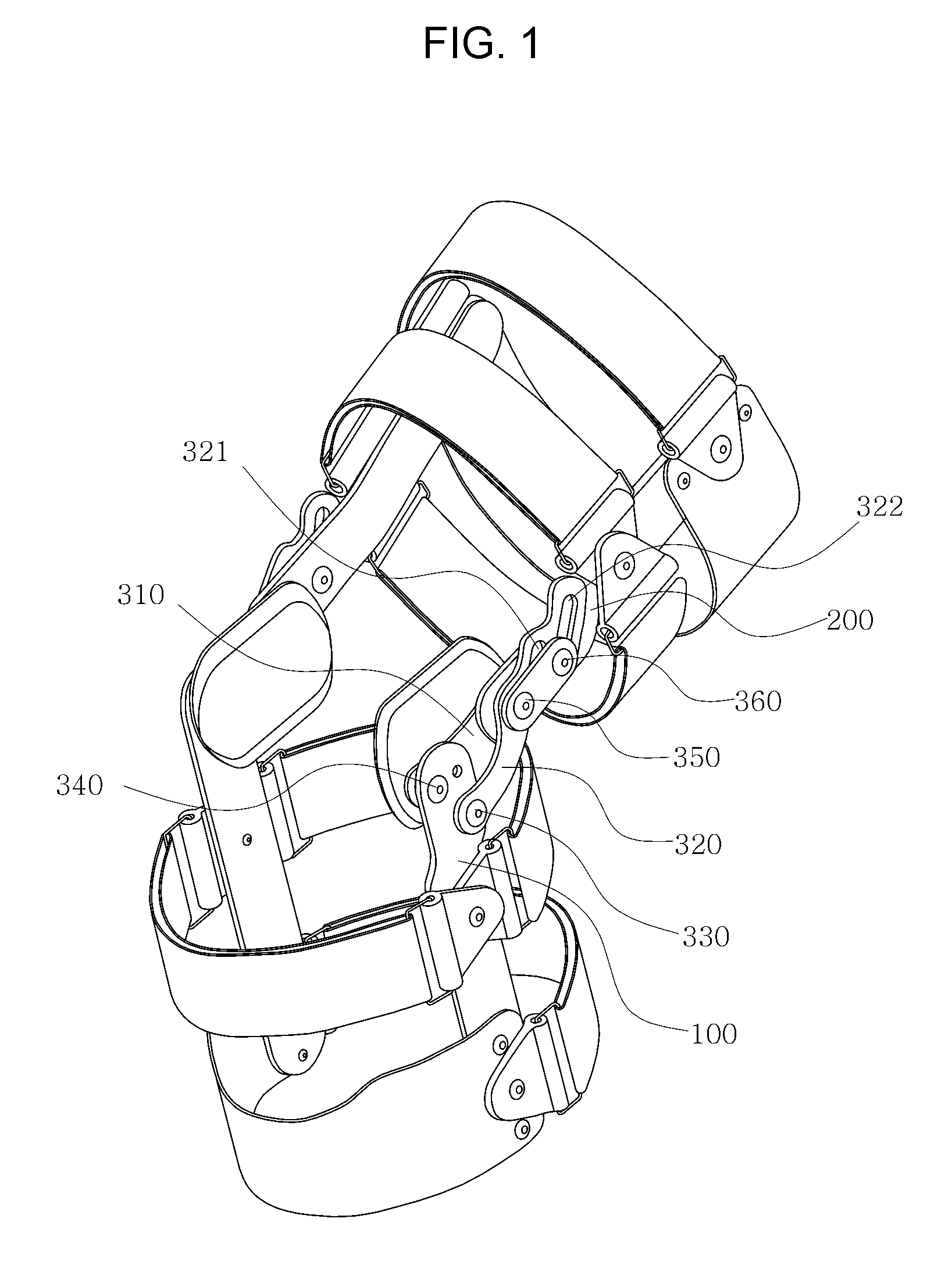
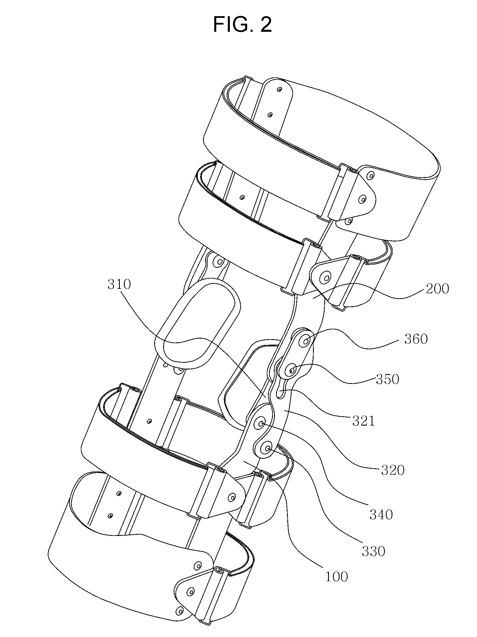
[0037]FIG. 1 illustrates a perspective view showing an orthopedic brace of a knee joint according to the first embodiment of the present invention. FIG. 2 illustrates another used state of the orthopedic brace shown in FIG. 1. FIG. 3 illustrates a side view of FIG. 1. FIGS. 4 to 7 illustrate side views showing the respective states in which the upper support member of FIG. 3 is moved by rotation angle displacements of 19°, 38°, 57° and 71°. FIG. 8 illustrates side views of essential parts showing a process in which the state of FIG. 3 is changed to the state of FIG. 7.

[0038]As shown in FIGS. 1 and 2, the first hinge assembly 300 includes a first link 310, a second link 320, a first hinge 330, a second hinge 340, a third hinge 350, and a rotation connector 360. The first hinge 330 connects the lower support member 100 with the se...

second embodiment

[0052]FIG. 9 illustrates a front view of an orthopedic brace of a knee joint according to the present invention. FIGS. 10A and 10B illustrate front views of essential parts of a second hinge assembly of FIG. 9 in a used state.

[0053]As shown in FIG. 9, the orthopedic brace of a knee joint according to the second embodiment of the present invention includes the first hinge assembly 300 of the first embodiment installed on the left side of the knee joint required to be supported upward in a vertical direction when the wearer stands up straight, and the second hinge assembly 400 installed on the right side of the knee joint required to be variably extended in a horizontal direction.

[0054]The second hinge assembly 400 largely includes a lower leaf spring 410, an upper leaf spring 420, a lower spring connecting portion 430 and an upper spring connecting portion 440. The lower leaf spring 410 and the upper leaf spring 420 are coupled to the lower support member 100 and the upper support me...


PUM


Abstract

An orthopedic brace of a knee joint is disclosed. The orthopedic brace including a hinge assembly connecting a lower support member and an upper support member to have a certain relative angle, wherein the hinge assembly includes a first link hinged to an upper portion of the lower support member and a lower portion of the upper support member, a second link hinged to the lower support member at a position spaced from the first link and having a linear slit and a curved slit spaced from the linear slit, a first hinge connecting the lower support member to the second link, a second hinge connecting the lower support member to the first link, a third hinge connecting the upper support member to the first link and slidably coupled to the linear slit, and a rotation connector coupled to the upper support member and slidably coupled to the curved slit.

Description

CROSS REFERENCE[0001]This application claims foreign priority under Paris Convention and 35 U.S.C. §119 to Korean Patent Application No. 10-2008-0003288, filed Jan. 11, 2008 with the Korean Intellectual Property Office.BACKGROUND OF THE INVENTION[0002]1. Field of the Invention[0003]The present invention relates to an orthopedic brace of a knee joint, and more particularly to an orthopedic brace of a knee joint provided at a knee portion to relieve the pain and to provide stability and correction of the knee joint.[0004]2. Description of the Related Art[0005]Generally, a brace of a knee joint is provided at a knee portion of a patient who has undergone orthopedic operation or treatment of a knee joint, a physically disabled person and old and weak people to control and stabilize movement of a knee joint and to correct a bent joint. The brace of a knee joint is also used to prevent a recurrence of knee damage.[0006]Particularly, a brace of a knee joint is provided for a bowlegged pati...

Claims


Application Information

Patent Timeline
Patent Type & Authority Applications(United States)
IPC IPC(8): A61F5/00
CPCA61F5/0123A61F2005/0174A61F2005/0165A61F2005/0137
Inventor CHO, SANG DEOG
Owner DAVINCIMEDITEC
Why Eureka
Try Eureka