Method and apparatus for determining the properties of drilling fluids

a technology of drilling fluid and properties, applied in the direction of surveying, instruments, borehole/well accessories, etc., can solve the problems of increasing the risk of losing drilling fluid (i.e., drilling “mud”), severe mud loss, and loss of the ability to control the well

Inactive Publication Date: 2011-01-18
MI
View PDF23 Cites 11 Cited by
  • Summary
  • Abstract
  • Description
  • Claims
  • Application Information

AI Technical Summary

Problems solved by technology

When drilling in depleted zones or otherwise weak formations, wellbore instability and formation damage are major concerns for operators.
However, drilling through such highly depleted zones may increase the risk of losing drilling fluid (i.e., drilling “mud”) through fractures or other features of the formation.
In high permeability formations, or where induced or natural fractures exist, whole drilling fluid may be lost into the formation during this stage which, if left uncontrolled, may continue and lead to severe mud losses and loss of the ability to control the well.
However, because formations and wellbores are unique, no single LPM configuration (e.g., material, size, concentration, etc.) will be optimal for all drilling conditions.
As such, the flow path through the ceramic media was relatively short and generally did not allow the mud rheology sufficient time to exert control over the loss of the fluid matrix.

Method used


Image

  • Method and apparatus for determining the properties of drilling fluids
  • Method and apparatus for determining the properties of drilling fluids
  • Method and apparatus for determining the properties of drilling fluids

Examples


Embodiment Construction

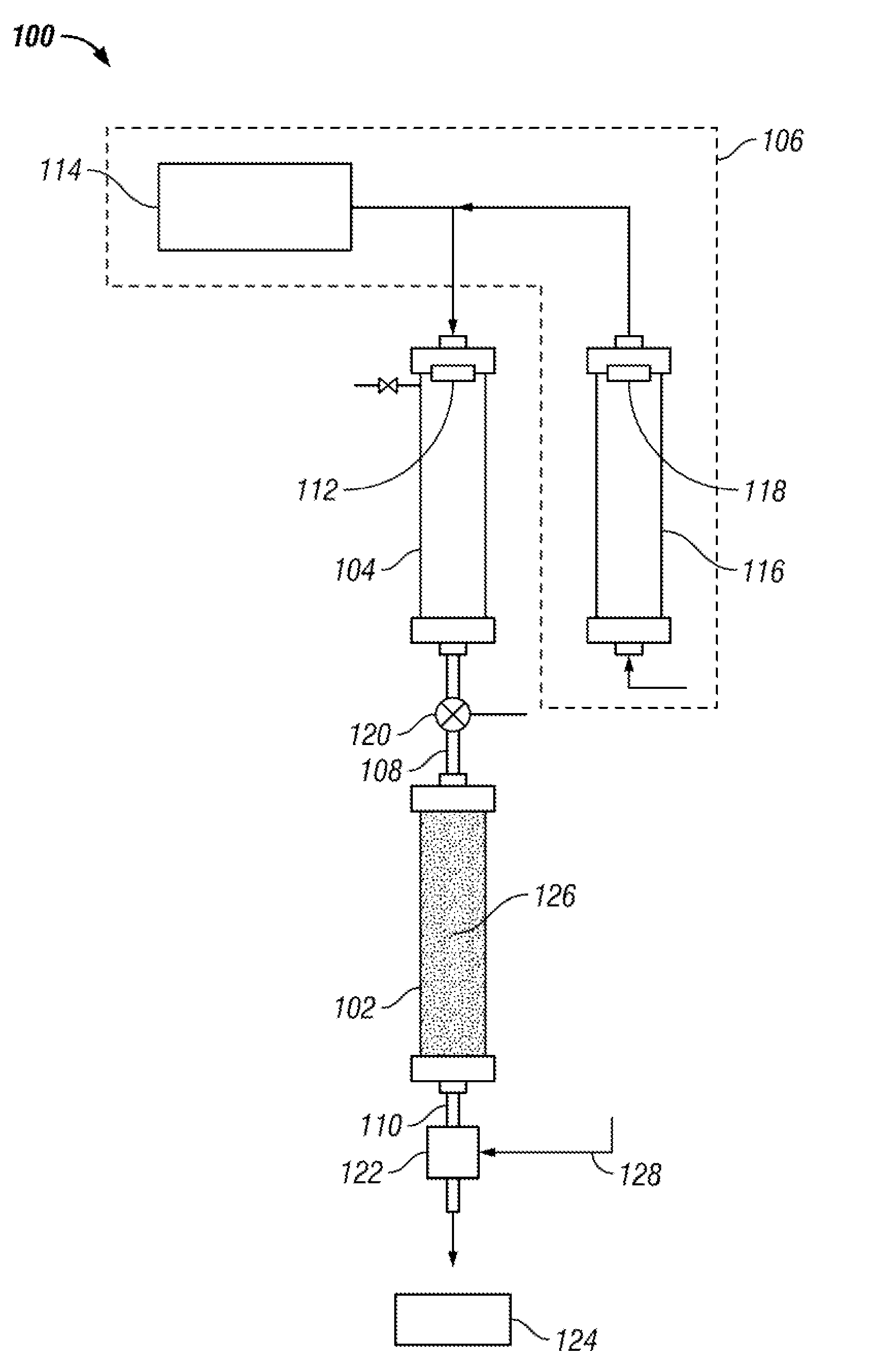
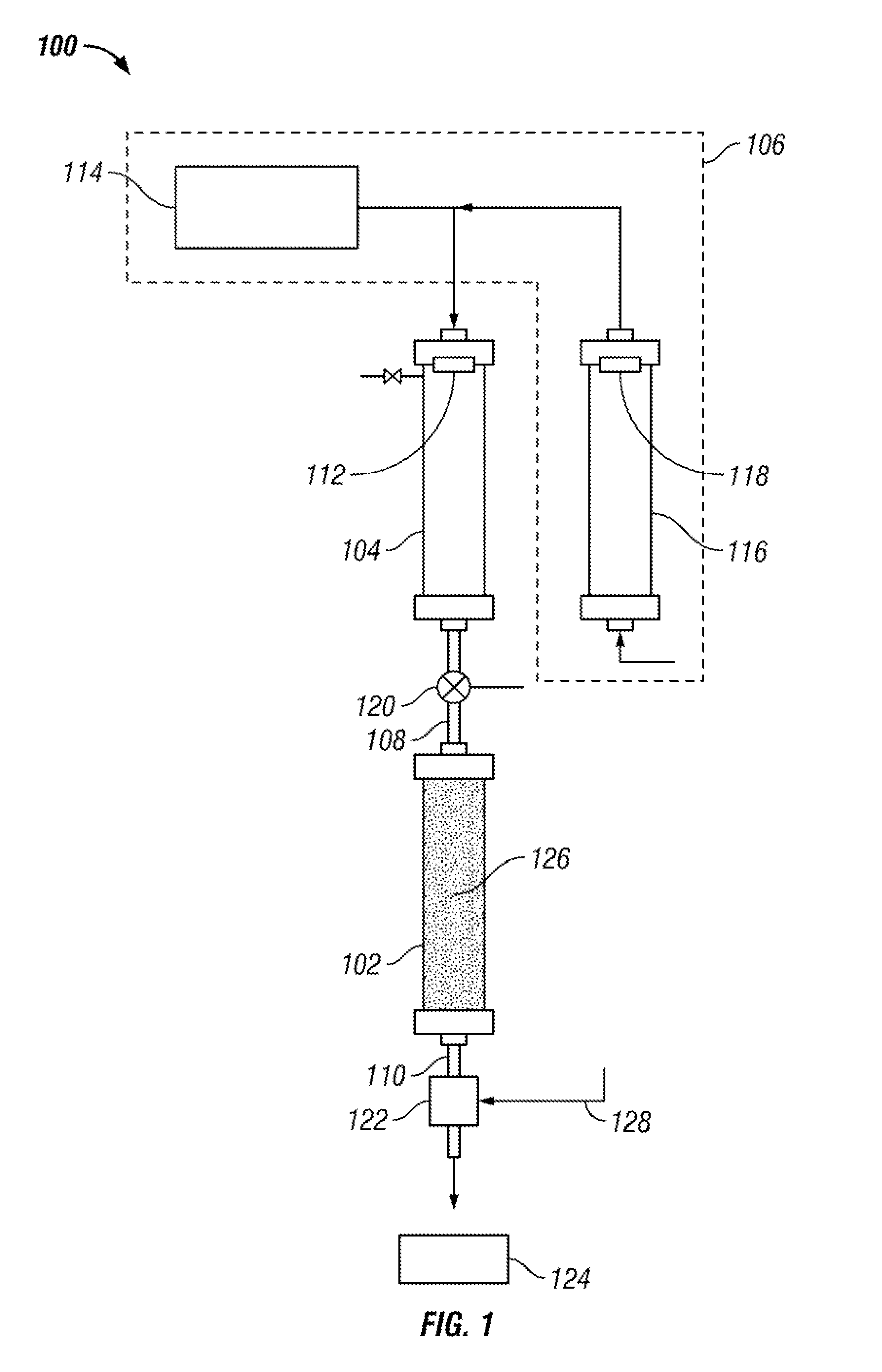
[0018]The present disclosure relates to methods and apparatus to evaluate matrix loss characteristics of drilling fluids under a variety of differential pressures. Selected embodiments include forcing a known volume of a drilling fluid through a porous medium of known permeability or mean pore size, by applying a known differential pressure across the matrix. A flow versus time profile of the fluid exiting the porous medium may be used to determine matrix loss characteristics of the drilling fluid composition being tested.

[0019]Referring initially to FIG. 1, an apparatus 100 to measure loss of a drilling fluid composition is shown schematically. As shown, measurement apparatus 100 includes a test housing 102, a fluid reservoir 104, and a pressure assembly 106. Test housing 102 is shown as a double-ended, high-temperature, high-pressure (“HTHP”) vessel having an inlet 108 at its upper end and an outlet 110 at its lower end. While test housing 102 is shown as a cylinder having an appr...


PUM


Abstract

Methods and apparatus to measure flow of a drilling fluid composition include a test housing including a test matrix located between an inlet and an outlet, a test valve connected between the inlet of the test housing and a fluid reservoir, and a pressure assembly configured to apply pressure to drilling fluid contained in the fluid reservoir. The apparatus and methods further include a sample valve connected to the outlet of the test housing and a measurement device configured to measure a filtrate fluid flowing through the outlet. A method to measure flow of a drilling fluid includes measuring an amount of filtrate fluid flowing through the test matrix as a function of time.

Description

CROSS-REFERENCE TO RELATED APPLICATIONS[0001]This applications claims priority, pursuant to 35 U.S.C. 119(e) to U.S. Provisional Patent Application No. 60 / 908,106, filed Mar. 26, 2007. That application is expressly incorporated by reference in its entirety.BACKGROUND[0002]1. Field of the Disclosure[0003]The present disclosure generally relates to apparatus and methods to test drilling fluids. More particularly, the present disclosure relates to methods and apparatus to measure the loss of drilling fluids through selected formations over time. More particularly still, the present disclosure relates to apparatus and methods to test the effectiveness of loss prevention materials entrained in drilling fluids against selected formations.[0004]2. Background Art[0005]When drilling in depleted zones or otherwise weak formations, wellbore instability and formation damage are major concerns for operators. Because of the economic incentives to extract as much of the hydrocarbon deposits from s...

Claims


Application Information

Patent Timeline
Patent Type & Authority Patents(United States)
IPC IPC(8): E21B49/02
CPCG01N15/06G01N15/08G01N33/2823
Inventor TEHRANI, MOSTAFA AHMADICAMERON, JACQUELINE JOAN
Owner MI
Why Eureka
Try Eureka