Skate with in-line rollers or ice blades

a technology of inline rollers and skates, applied in the direction of roller skates, skate boards, sport equipment, etc., can solve the problems of insufficient loading of two carriages, inability to adequately control the carriage of skaters, and instability of the toe portion, so as to eliminate or drastically reduce the instability of the same skate

Inactive Publication Date: 2011-01-18
CONTINENTAL TEVES AG & CO OHG +1
View PDF59 Cites 4 Cited by
  • Summary
  • Abstract
  • Description
  • Claims
  • Application Information

AI Technical Summary

Benefits of technology

[0005]It therefore is a main object of the present invention to effectively do away with the above-cited drawbacks of prior-art solutions by providing a skate with in-line rollers or ice-skating blades, comprising a chassis for supporting the rollers, or the blades, which includes first and second carriages that are both capable of moving relative to each other, wherein directing, driving and controlling the skate can be ensured in an optimum manner throughout the skating stride, and in particular during the initial pushing and final phases thereof, thereby eliminating or at least drastically reducing the instability of the same skate.

Problems solved by technology

This practically means that, at any moment throughout skating, one of the two carriages is not being loaded adequately, with the possibility for it to freely pivot about the hinging pin connecting it to the chassis in the initial and final thrust phases.
This obviously involves the skater being substantially unable to adequately control the carriage not being loaded, and this is exactly what determines the afore-mentioned instability of the skate, particularly when skating at a high speed.
This most obviously involves a clear difficulty in riding, directing and controlling the skate in said phases: in fact, the sole rear rollers being in contact in the initial pushing phase is instrumental in determining a condition of instability of the toe portion exactly when the maximum force is being applied, whereas the sole front rollers being on the contrary in contact during the final phase causes again a condition of instability to arise in the toe portion due to no rest, i.e. backing, being available at the rear when the force applied by the foot is eventually fully removed.

Method used


Image

  • Skate with in-line rollers or ice blades
  • Skate with in-line rollers or ice blades
  • Skate with in-line rollers or ice blades

Examples


second embodiment

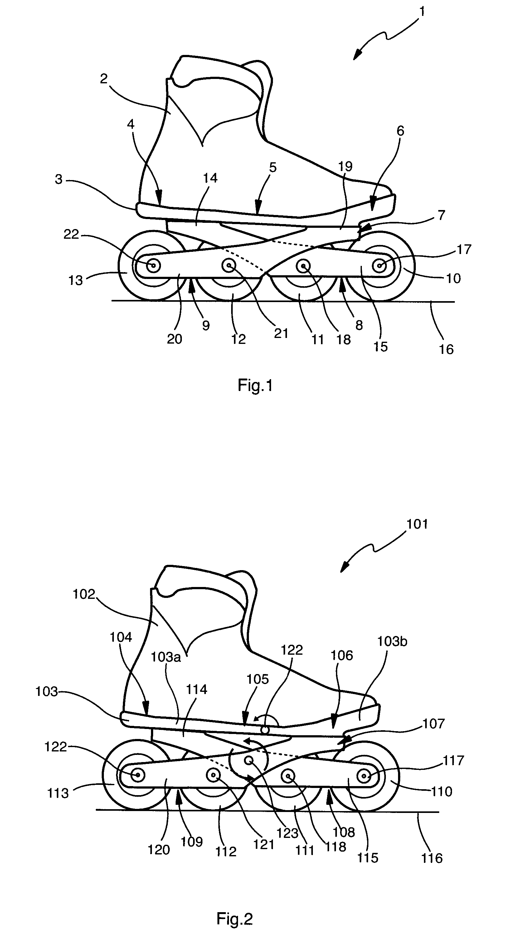
[0028]So, for instance, FIG. 2 illustrates a second embodiment in which, in view of further enhancing both skate control and skating efficiency, the sole 103 of the footwear item 102 is made so as to be pliable, i.e. capable of bending, so as to be able to follow the natural motion of the foot during the skating stride, and the first carriage 108 is connected to the second carriage 109, while anyway maintaining the capability of moving relative to each other.

[0029]To such purpose, the sole 103 is made so as to be comprised of a rear part 103a, which includes the heel portion 104 and the rear portion of the central portion 105, and a front part 103b, which includes the front portion of the central portion 105 and the toe portion 106, said two parts being pivotally connected to each other by means of first hinge means 122 that are advantageously positioned in the central portion 105 at a site approximately corresponding to the articulation zone of the foot.

[0030]To the first carriage ...

third embodiment

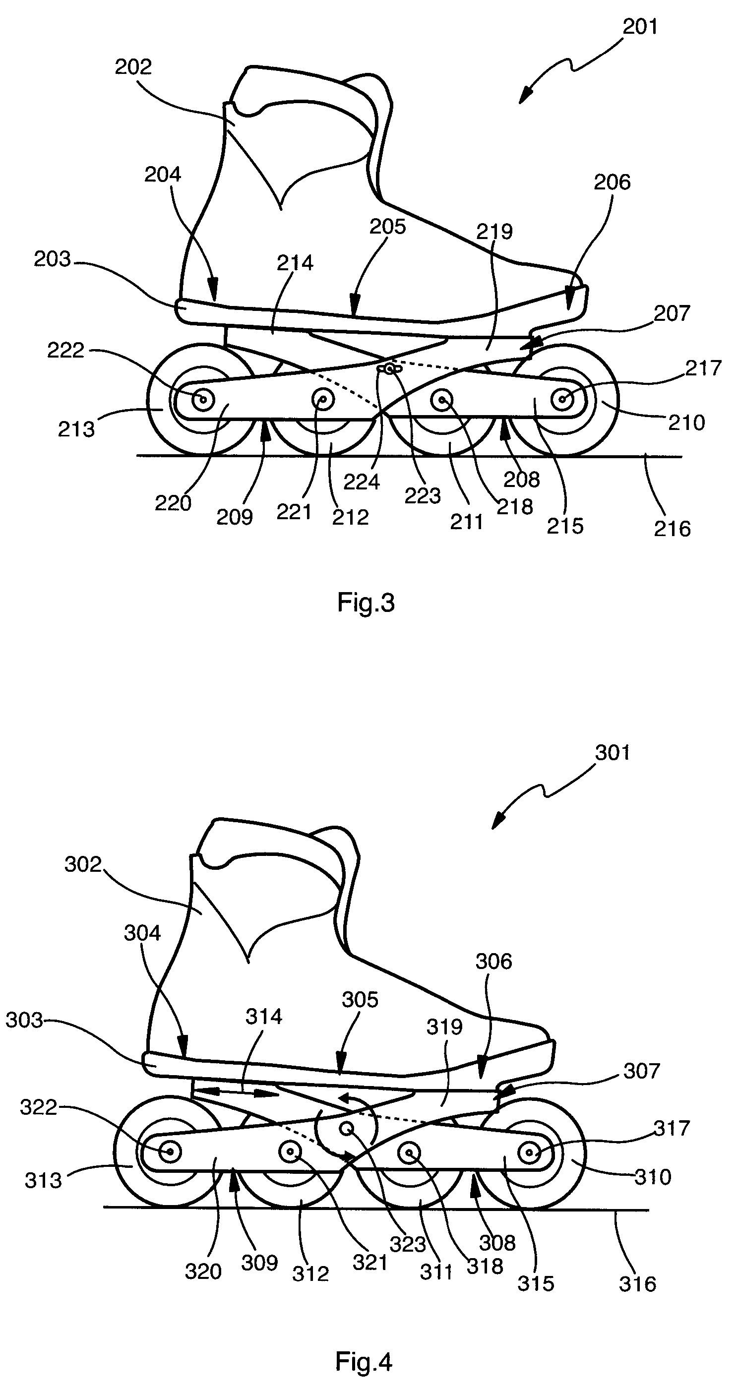
[0032]FIG. 3 illustrates the skate according to the present invention, in which the sole 203 is preferably rigid; the first carriage 208 and the second carriage 209 are pivotally and slidably connected to each other by means of a pin-and-slot arrangement 223, 224.

[0033]Shown in FIG. 4 is a fourth embodiment of the skate according to the present invention, this fourth embodiment being substantially similar to the previous one, except for the fact that the above-mentioned pin-and-slot arrangement is in this case subdivided into a hinge 323, ensuring the pivoting connection between the first carriage 308 and the second carriage 309, and a sliding coupling between the first plate 314 and the sole 303 at the heel portion 304. As an alternative thereto, such sliding coupling may be provided between the second plate 319 and the toe portion 306.

fifth embodiment

[0034]The illustration in FIG. 5 refers to the skate according to the present invention, in which at least one of the first carriage 408 and the second carriage 409 is provided with an appendix extending upwards from the first arm 415 or the second arm 420, as the case may be, to interact with the second plate 419 or the first plate 414, respectively, via at least an elastic or vibration-damping member interposed therebetween. The two carriages 408 and 409 are coupled to each other by means of a hinge 423, and the sole 403 may be either rigid or pliable, either elastically or by means of a hinge in accordance with what has been illustrated and described in connection with the embodiment shown in FIG. 2. It will be readily appreciated that a number of different options are feasible to implement such connection between the carriages 408 and 409, according to what has been described with reference to the other embodiments illustrated hereinbefore.

[0035]In the case of the embodiment sho...


PUM


Abstract

The present invention refers to a skate with in-line rollers or ice-skating blades, comprising: a boot provided with a sole comprising a heel portion, a central portion and a toe portion; a chassis acting as a support for said sole to rest thereupon, and including a first carriage and a second carriage that are capable of moving relative to each other and adapted to support at least a front roller or blade and at least a rear roller or blade respectively; the first carriage comprises a first plate for said heel portion to rest thereupon, from which there extends towards the front portion of the skate a first arm that is adapted to support at least said front roller or blade, and the second carriage comprises a second plate for the toe portion to rest thereupon, from which there extends towards the rear portion of the skate a second arm that is adapted to support at least said rear roller or blade; the first and second carriages overlap each other approximately at the central portion of the sole.

Description

FIELD OF THE INVENTION[0001]The present invention refers to a skate provided with at least two rollers in an axially in-line arrangement relative to the skate, or an ice skate provided with at least two blades. The skate comprises a chassis for supporting the rollers, or the blades, which includes first and second rolling or sliding units, or carriages as they will be generally referred to hereinafter, that are movable relative to each other.BACKGROUND OF THE INVENTION[0002]Some kinds of skates, mainly with in-line rollers, are already known in the art to be provided with a chassis including two carriages that are movable relative to each other. So, for instance, the French patent application No. 96 01439 discloses a skate with four in-line rollers mounted in a two-by-two arrangement to a front carriage and a rear carriage, respectively. The two carriages are pivotally hinged on to a chassis, on which the footwear thereabove is intended to rest. The two carriages cross each other in...

Claims


Application Information

Patent Timeline
Patent Type & Authority Patents(United States)
IPC IPC(8): A63C17/00
CPCA63C17/0046A63C17/062
Inventor ZAMPIERI, CLAUDIO
Owner CONTINENTAL TEVES AG & CO OHG
Why Eureka
Try Eureka