
Bicycle rear sprocket assembly

a rear derailleur and bicycle technology, applied in mechanical equipment, transportation and packaging, transportation equipment, etc., can solve the problems of sprocket deflection towards the adjacent sprocket, affecting the shifting performance of the rear derailleur, and increasing the weight of the bicycle, so as to resist the deflection of the sprock

Inactive Publication Date: 2011-01-18
SHIMANO INC
View PDF30 Cites 57 Cited by
  • Summary
  • Abstract
  • Description
  • Claims
  • Application Information

AI Technical Summary

Benefits of technology

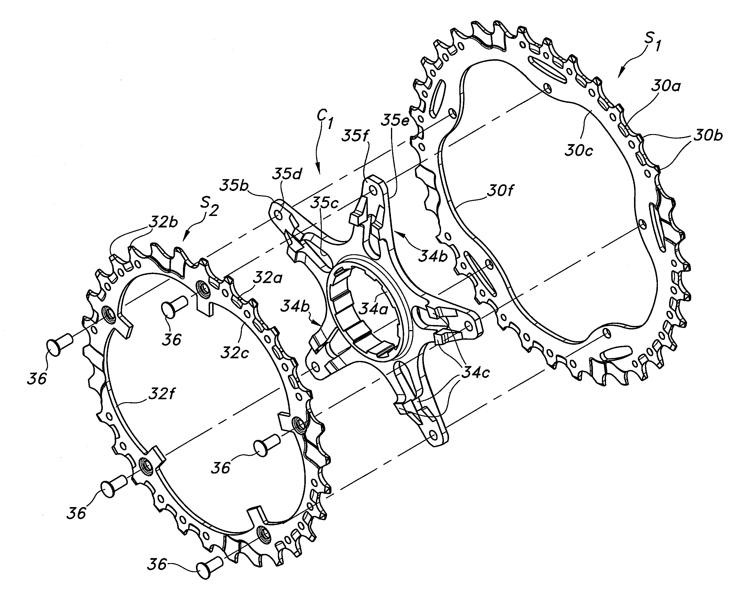
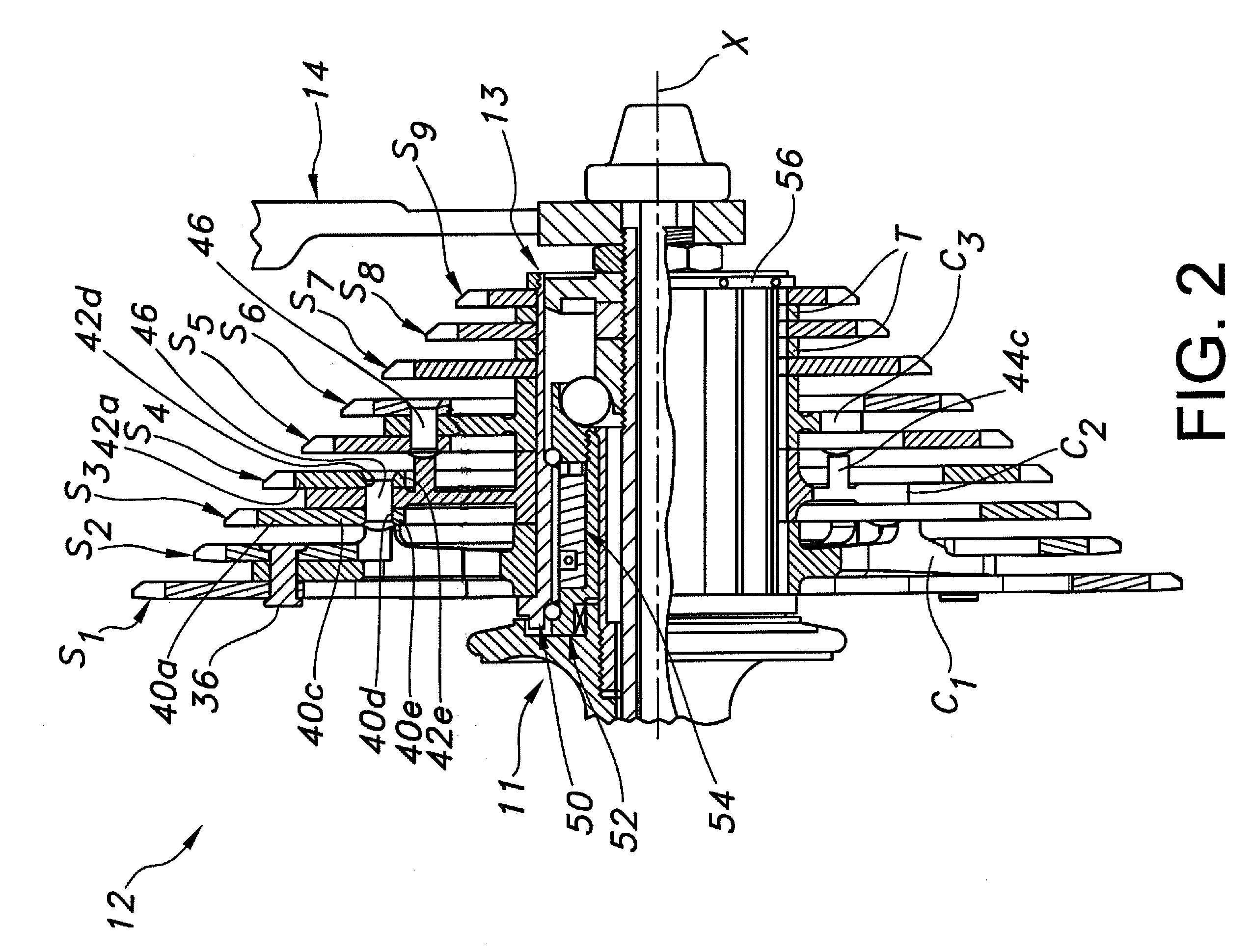
The present invention provides a bicycle rear sprocket assembly that is lightweight, strong, and resistant to deflection during shifting. The assembly includes a sprocket carrier, three sprockets (a first, second, and third), and attachment members that secure the sprockets to the carrier. The first and second sprockets have a similar number of teeth, while the third sprocket has fewer teeth. The attachment members are attached to the outer end of the sprocket carrier using a common fastener. The second attachment member has a free edge that is at least half the size of the fastener. The assembly also includes space maintaining projections on one or more of the attachment members, sprockets, or both. The technical effects of this invention include relatively lightweight and strong rear sprocket assembly that is resistant to deflection during shifting, as well as easy and inexpensive manufacturing and assembly.

Problems solved by technology

As a result, the weight of the bicycle has increased.
However, one drawback of a multiple sprocket assembly constructed in this manner is that if the spider is made too thin, then the sprocket may deflect towards the adjacent sprocket.
This situation can result in degrading the shifting performance of the rear derailleur.
On the other hand, if the spider is made thicker, weight of the multiple sprocket assembly increases.

Method used


Image

  • Bicycle rear sprocket assembly
  • Bicycle rear sprocket assembly
  • Bicycle rear sprocket assembly

Examples


Embodiment Construction

[0041]Selected embodiments of the present invention will now be explained with reference to the drawings. It will be apparent to those skilled in the art from this disclosure that the following descriptions of the embodiments of the present invention are provided for illustration only and not for the purpose of limiting the invention as defined by the appended claims and their equivalents.

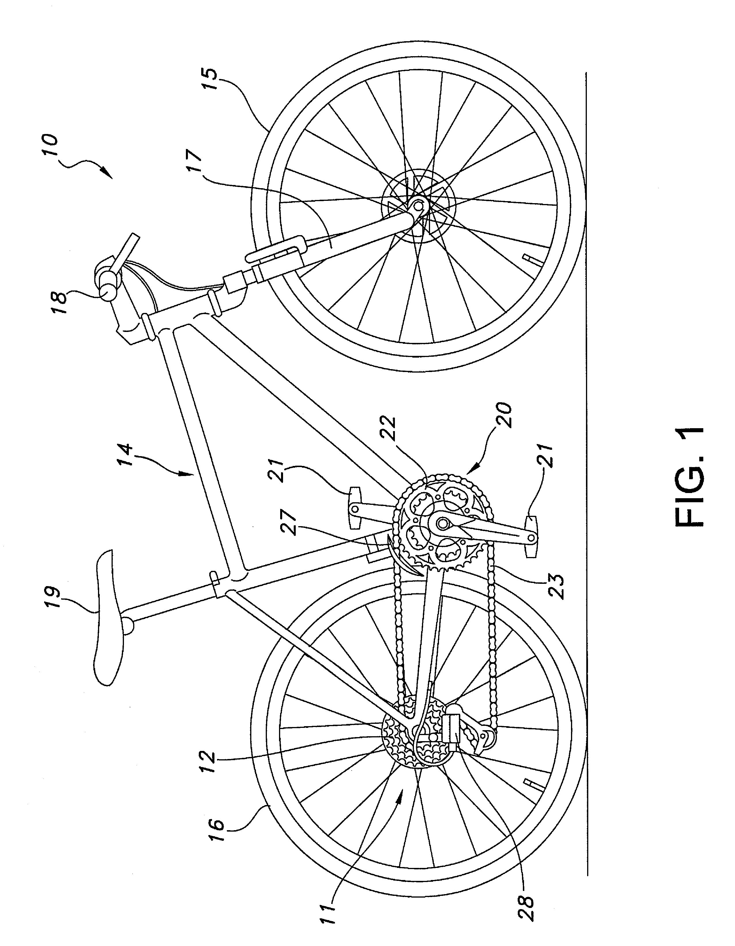
[0042]Referring initially to FIGS. 1 and 2, a conventional bicycle 10 is illustrated having a rear bicycle hub 11 with a rear multi-stage sprocket assembly 12 mounted on a freewheel 13 in accordance with the present invention. The bicycle 10 basically has a frame 14 with front and rear wheels 15 and 16 rotatably coupled thereto. A front fork 17 is coupled between the frame 14 and the front wheel 15 in a conventional manner. Turning a handlebar 18, which is fixedly coupled to the front fork 17, turns the front wheel 15. The rear wheel 16 is rotatably coupled to a rear portion of the frame 14 via the...


PUM


Abstract

A bicycle rear sprocket assembly has a sprocket carrier, a first sprocket, a second sprocket and a third sprocket. The first and second sprockets are attached to opposite axial sides of the outer end portion of the attachment member of the sprocket carrier using a common fastener that extends through the first and second attachment portions and the outer end portion of the attachment member. The third sprocket is disposed on adjacent the second sprocket. The second sprocket has a free edge spaced radially inwardly from the common fastener by a distance at least as large as one-half of a maximum transverse dimension of the fastener measured in a direction perpendicular to the rotation axis. At least one space maintaining projection extends axially toward an adjacent one of the second and third sprockets.

Description

BACKGROUND OF THE INVENTION[0001]1. Field of the Invention[0002]This invention generally relates to multiple sprocket assemblies for bicycles. More specifically, the present invention relates to a bicycle rear sprocket assembly that is configured to minimize bending of and maintain proper spacing between the sprockets.[0003]2. Background Information[0004]Bicycling is becoming an increasingly more popular form of recreation as well as a means of transportation. Moreover, bicycling has become a very popular competitive sport for both amateurs and professionals. Whether the bicycle is used for recreation, transportation or competition, the bicycle industry is constantly improving the various components of the bicycle to meet the demands of the riders.[0005]In recent years, as the number of speeds available in bicycle transmissions has increased, the number of sprockets installed on the rear-wheel sprocket assembly of such bicycles has increased seven sprocket wheels or more. As a resul...

Claims


Application Information

Patent Timeline
Patent Type & Authority Patents(United States)
IPC IPC(8): F16H55/12F16H55/30
CPCB62M9/10
Inventor KAMADA, KENJI
Owner SHIMANO INC
Learn More