Balanced-unbalanced conversion element

a technology of unbalanced and balanced elements, applied in the direction of waveguides, waveguide devices, electrical devices, etc., to achieve the effect of correcting the asymmetry of the electromagnetic field distribution

Inactive Publication Date: 2011-01-25
MURATA MFG CO LTD
View PDF6 Cites 0 Cited by
  • Summary
  • Abstract
  • Description
  • Claims
  • Application Information

AI Technical Summary

Benefits of technology

[0011]Accordingly, an object of the present invention is to provide a balanced-unbalanced conversion element that gives an appropriate balance characteristic over a wide frequency band by setting of a shape of an unbalanced pattern.
[0014]Accordingly, in this invention, a gap between the first open-end-side line and the first ¼-wavelength resonant line is set to be different from a gap between the second open-end-side line and the second ¼-wavelength resonant line. The gaps of the lines make capacitance values between the respective lines asymmetric. The degree of coupling between respective resonators also becomes asymmetric. By appropriately adjusting a balance of these line gaps, asymmetry of the electromagnetic field distribution can be corrected. Accordingly, the balanced-unbalanced conversion element can provide two balanced signals whose phase difference and amplitude difference converge to a predetermined range over a wide frequency band by appropriately balancing the phase difference and the amplitude difference of the two balanced signals of the balanced-unbalanced conversion element.
[0015]Additionally, in this invention, a width of the first open-end-side line is set to be different from a width of the second open-end-side line. These line widths allow the ½-wavelength resonant line to have a step structure and the resonator length changes. In accordance with this change, a position of an equivalent short-circuited end of the ½-wavelength resonant line changes. By appropriately balancing each line width, asymmetry of the electromagnetic field distribution can be corrected. Accordingly, the balanced-unbalanced conversion element can provide two balanced signals whose phase difference and amplitude difference converge to a predetermined range over a wide frequency band by appropriately balancing the phase difference and the amplitude difference of the two balanced signals of the balanced-unbalanced conversion element.
[0016]A balance-characteristic adjusting electrode whose distal end faces a side of the ½-wavelength resonant line and whose proximal end is connected to a ground electrode may be further included. By providing the balance-characteristic adjusting electrode, capacitance is provided at the side of the ½-wavelength resonant line and this capacitance changes a position of an equivalent short-circuited end. By appropriately setting the magnitude and position of the capacitance provided by the balance-characteristic adjusting electrode, asymmetry of the electromagnetic field distribution can be corrected. Accordingly, the balanced-unbalanced conversion element can provide two balanced signals whose phase difference and amplitude difference converge to a predetermined range over a wide frequency band by appropriately balancing the phase difference and the amplitude difference of the two balanced signals of the balanced-unbalanced conversion element.
[0017]A balanced-unbalanced conversion element according to this invention can provide two balanced signals having opposite phases over a wide frequency band by appropriately setting a phase difference and an amplitude difference of the two balanced signals.

Problems solved by technology

Conversely, in response to input of balanced signals to the two balanced terminals, the balun converts the balanced signals into an unbalanced signal and outputs the unbalanced signal from the unbalanced terminal.

Method used


Image

  • Balanced-unbalanced conversion element
  • Balanced-unbalanced conversion element
  • Balanced-unbalanced conversion element

Examples


Embodiment Construction

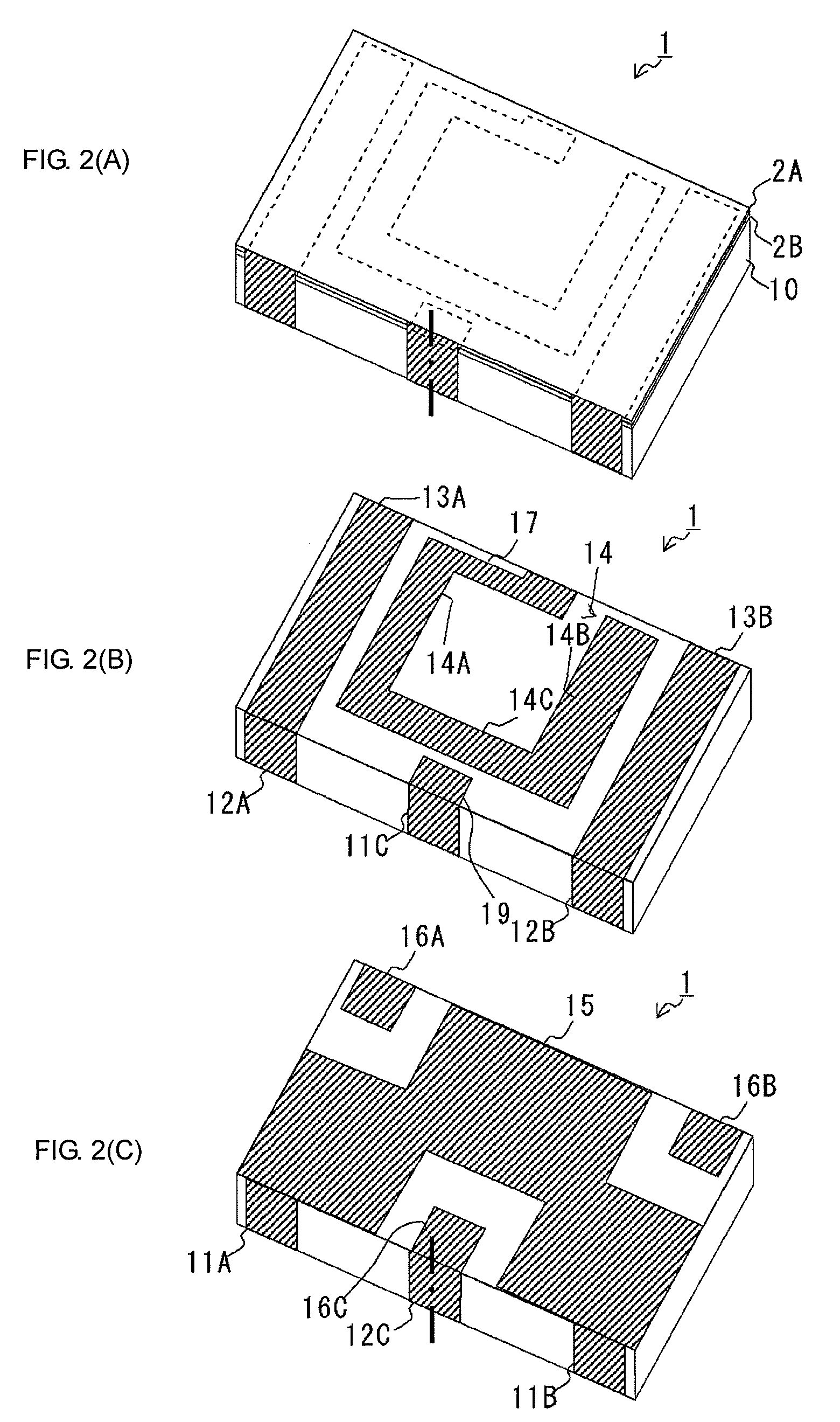
[0034]FIGS. 2(A) to 2(C) are diagrams illustrating a configuration of a balanced-unbalanced conversion element. More specifically, FIG. 2(A) is a perspective view of an upper-surface side of the balanced-unbalanced conversion element. A left proximal-side surface in the drawing corresponds to a front-side surface of the balanced-unbalanced conversion element, whereas a right proximal-side surface in the drawing corresponds to a right lateral-side surface of the balanced-unbalanced conversion element.

[0035]A balanced-unbalanced conversion element 1 is a small rectangular parallelepiped balun element for use in ultra wide band (UWB) communication. An upper surface of a rectangular flat-plate dielectric substrate 10 of this balanced-unbalanced conversion element 1 is covered with glass layers 2A and 2B. The glass layer 2B is a light-transmissive glass layer, whereas the glass layer 2A is a light-shielding glass layer.

[0036]Thickness of the dielectric substrate 10 is 500 μm, whereas thi...


PUM


Abstract

A balanced-unbalanced conversion element for realizing easy adjustment of a phase balance of two balanced signals is provided. The balanced-unbalanced conversion element includes a first ¼-wavelength resonant line coupled to a first balanced terminal, a second ¼-wavelength resonant line coupled to a second balanced terminal, and a ½-wavelength resonant line. The ½-wavelength resonant line includes a first open-end-side line coupled to an unbalanced terminal and the first ¼-wavelength resonator and a second open-end-side line coupled to the second ¼-wavelength resonator. In addition, a width of the first open-end-side line differs from a width of the second open-end-side line.

Description

CROSS REFERENCE TO RELATED APPLICATIONS[0001]The present application is a continuation of International Application No. PCT / JP2008 / 059432, filed May 22, 2008, and claims priority to Japanese Patent Application No. JP2007-183823, filed Jul. 13, 2007, the entire contents of each of these applications being incorporated herein by reference in their entirety.FIELD OF THE INVENTION[0002]The present invention relates to a balanced-unbalanced conversion element including balanced terminals and an unbalanced terminal.BACKGROUND OF THE INVENTION[0003]A balanced-unbalanced conversion element that has one ½-wavelength resonator and two ¼-wavelength resonators formed on a dielectric substrate and performs balanced-unbalanced conversion has been suggested (see, for example, Patent Document 1).[0004]FIG. 1 shows a configuration of a balun serving as a balanced-unbalanced conversion element according to the related art. A balun 101 is formed of a plurality of laminated dielectric substrates. This ...

Claims


Application Information

Patent Timeline
Patent Type & Authority Patents(United States)
IPC IPC(8): H03H7/42H01P3/08
CPCH01P5/10
Inventor MORI, HIROTSUGUHIROSHIMA, MOTOHARU
Owner MURATA MFG CO LTD
Why Eureka
Try Eureka