Apparatus and method for correcting unsymmertry of light disk regenerating system

A regeneration system and symmetry technology, applied in the field of RF signal asymmetry devices, can solve the problem that the limiter reference level is difficult to follow the middle level of the RF signal, the data cannot be detected, and the disc material is not good for disc punching And other issues

Inactive Publication Date: 2005-04-20
SAMSUNG ELECTRONICS CO LTD
View PDF0 Cites 0 Cited by
  • Summary
  • Abstract
  • Description
  • Claims
  • Application Information

AI Technical Summary

Problems solved by technology

Here, a hole defect is where the disc material is not good or the disc is drilled so deep that light passes through the disc without being reflected
Thus, the data cannot be detected
[0008] Then, in the portion where there is a scratch or a hole, since the asymmetry of the RF signal may be incorrectly corrected, an error correcting portion (not shown) connected to a conventional asymmetry correcting device cannot correctly correct the error.
[0009] Since the time constants of the resistors R5 and R6 and the capacitors C2 and C3 of the low-pass filter 16 are, for example, 5 ms, it is difficult for the clipping reference level to follow the RF signal much shorter than 5 ms at the portion where there are scratches or holes. mid level

Method used


Image

  • Apparatus and method for correcting unsymmertry of light disk regenerating system
  • Apparatus and method for correcting unsymmertry of light disk regenerating system
  • Apparatus and method for correcting unsymmertry of light disk regenerating system

Examples


Embodiment Construction

[0034]Referring to the accompanying drawings, the structure and operation of each of the asymmetry correcting device and asymmetry correcting method for an optical disc reproduction system according to the present invention will be described as follows.

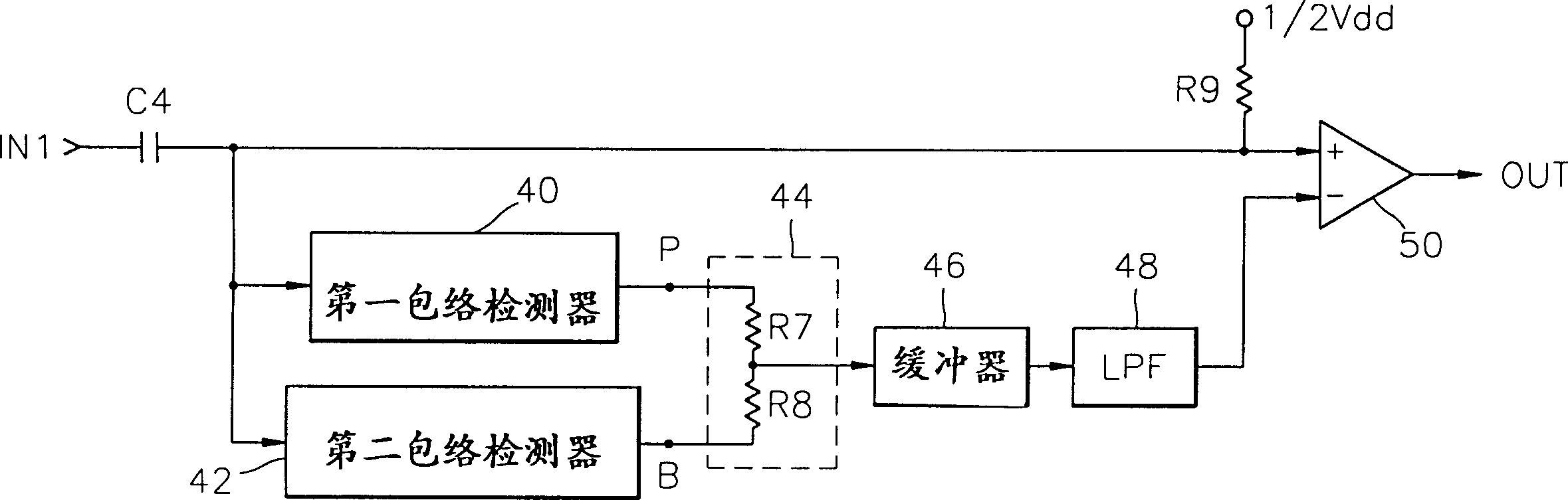
[0035] figure 2 is a block diagram of an apparatus for correcting asymmetry of an optical disc reproduction system according to an embodiment of the present invention. The arrangement comprises a capacitor C4, first and second envelope detectors 40 and 42, a level controller 44 consisting of resistors R7 and R8, a buffer 46, a low-pass filter (LPF) 48, a resistor R9, and comparator 50 .

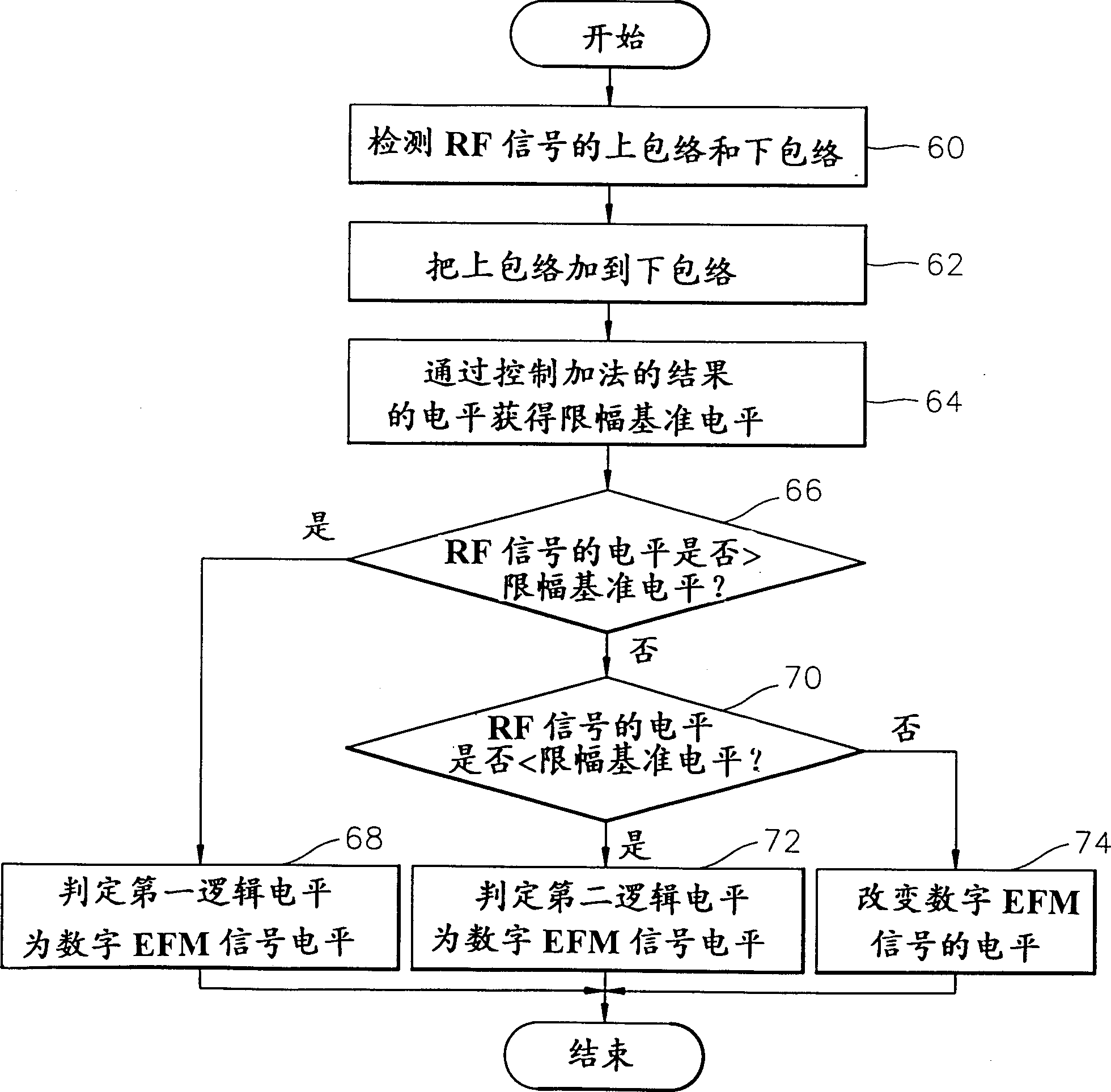
[0036] image 3 is described according to the present invention in figure 2 Flowchart of the asymmetry correction method implemented in the device shown in . The method includes the steps of obtaining a clipping reference level using the detected envelope from the RF signal (steps 60 to 64), and determining a digital EFM signal level bas...


PUM


Abstract

Apparatus and method for correcting asymmetry in an optical disc reproduction system. The device for correcting the asymmetry of the RF signal received from the optical diode and outputting the asymmetry-corrected signal as a digital EFM signal, the device comprising an envelope detector for detecting the upper and lower envelopes of the RF signal, A controller for controlling the level of the sum of the upper and lower envelopes and outputting a signal having the controlled level, and for comparing the level of the signal output from the level controller with the level of the RF signal and serving as A comparator that outputs a comparison result for a digital EFM signal.

Description

technical field [0001] The present invention relates to optical disc reproduction systems, and more particularly to an apparatus and method for correcting the asymmetry of an RF signal output from a photodiode in an optical disc reproduction system. Background technique [0002] In an optical disc reproduction system, an asymmetry correcting device corrects the asymmetry of an RF signal and converts the RF signal into a digital eight to fourteen modulated (EFM) signal. That is, the asymmetry correcting means clips the RF signal output from the optical diode based on the clip reference level at which the asymmetry is corrected, and obtains a digital EFM signal. The 'EFM comparator (CXA12710)' shown on page 89 of "SONY SEMICONDUCTORIC DATABOOK" published by 'SONY' in 1990 (hereinafter referred to as a conventional asymmetry reference device) is an example of such an asymmetry correction device. [0003] The structure and operation of a conventional asymmetry correcting device...

Claims


Application Information

Patent Timeline
Patent Type & Authority Patents(China)
IPC IPC(8): G11B7/00G11B7/005G11B20/10
CPCG11B7/005G11B20/10009G11B7/00
Inventor 金济国张荣旭李锡政
Owner SAMSUNG ELECTRONICS CO LTD
Why Eureka
Try Eureka