End cover for electric machine, electric machine and method for assembling electric machine

A technology of end caps and support elements, applied in the fields of end caps for motors, motors and for assembling motors, to achieve the effect of correcting asymmetry

Active Publication Date: 2017-05-31
MAN ENERGY SOLUTIONS SA
View PDF5 Cites 0 Cited by
  • Summary
  • Abstract
  • Description
  • Claims
  • Application Information

AI Technical Summary

Problems solved by technology

[0010] Due to manufacturing and assembly tolerances being taken into account in principle, it is practically impossible to prevent that the center of the magnetic bearing, which supports the rotor in the end shield, does not coincide exactly with the magnetic longitudinal axis of the stator winding of the stator

Method used


Image

  • End cover for electric machine, electric machine and method for assembling electric machine
  • End cover for electric machine, electric machine and method for assembling electric machine
  • End cover for electric machine, electric machine and method for assembling electric machine

Examples


Embodiment approach

[0068] According to one embodiment of the invention, this is achieved by means of the following method steps performed successively:

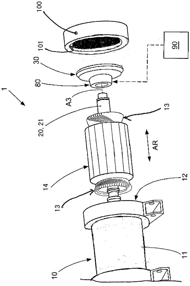
[0069] By measuring the inner circumference 12 of the stator housing 11 (for example by means of a 3D coordinate measuring machine), the position of the geometrical longitudinal axis A2 of the inner circumference 12 of the stator housing 11 is determined. The outer circumference contour of the end shield 30 is fitted into the inner circumference 12 of the stator housing 11 in a roughly adjusted manner. To this end: by measuring the bearing receptacle 40 of the end shield 30 , the position of the center of the magnetic bearing 80 is determined relative to the position of the geometrical longitudinal axis A2 of the inner circumference 12 of the stator housing 11 . The value of the offset of the center of the magnetic bearing 80 relative to the geometrical longitudinal axis A2 of the inner circumference 12 of the stator housing 11 is then determin...


PUM


Abstract

An end plate for an electric machine includes: a bearing receptacle in which a magnetic bearing which is configured for rotatably mounting a rotor of the electric machine can be accommodated; and a radially outwardly pointing circumferential contour on which a number of at least three supporting elements are provided, which supporting elements each protrude radially beyond the circumferential contour by a determined protruding amount, with the result that the supporting elements define a discontinuous external circumferential contour of the end plate. The respective protruding amounts of the support elements are dimensioned such that the end plate can be fitted in by making a center of the magnetic bearing correspond to at least one of a geometric longitudinal axis of the electric machine and a magnetic longitudinal axis of the electric machine.

Description

technical field [0001] The invention relates to an endshield for an electric machine, an electric machine equipped with such an endshield, and a method for assembling an electric machine. Background technique [0002] From DE 10 2009 001 948 A1 an end shield for an electric motor is known which has an inner ring as a bearing receptacle in which a rotor provided for rotatably mounting the electric motor can be accommodated bearing, the end shield also has an outer ring as a radially outwardly directed outer circumferential contour, which can be fitted under prestressing into the interior of the stator housing of the electric machine in order to radially support the end shield in the circumference. [0003] From DE 10 2009 019 593 A1 it is known an electric motor with a stator with a stator housing, a rotor arranged in the inner circumference of the stator housing and an end cap in which a rotatable rotor is accommodated. Bearings supported in a bearing receiver. An active ...

Claims


Application Information

Patent Timeline
Patent Type & Authority Patents(China)
IPC IPC(8): H02K15/16H02K7/09H02K5/15H02K5/16
CPCF16C23/00F16C32/047H02K5/15H02K5/161H02K7/09H02K15/16H02K2213/09Y10T29/49011H02K15/02
Inventor G.卡布斯G.克利恩汉斯M.德特维勒M.韦特
Owner MAN ENERGY SOLUTIONS SA
Why Eureka
Try Eureka