
Methods for cleaning out horizontal wellbores using coiled tubing

a technology of coiled tubing and wellbore, which is applied in the direction of fluid removal, cleaning process and apparatus, borehole/well accessories, etc., can solve the problems of high potential for premature screening, increased complexity of reliable execution of fracturing process, and disadvantages of traditional cleaning methods, and achieves the effect of efficient ra

Active Publication Date: 2011-02-01
BAKER HUGHES INC
View PDF20 Cites 16 Cited by
  • Summary
  • Abstract
  • Description
  • Claims
  • Application Information

AI Technical Summary

Benefits of technology

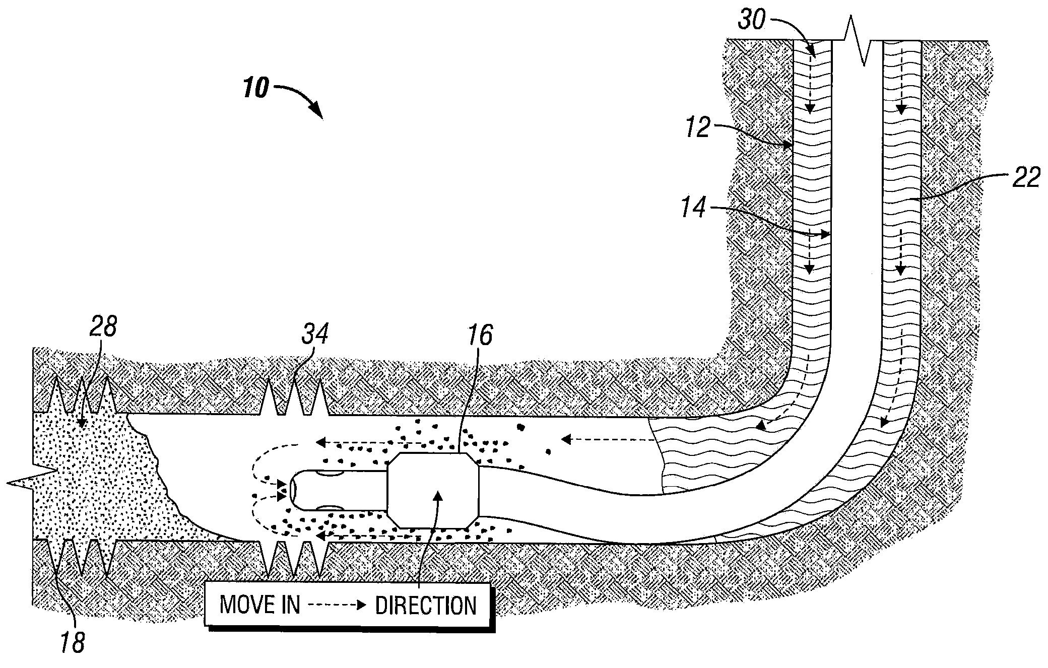
[0010]Various embodiments of the present invention provide methods for cleaning out horizontal wellbores using coiled tubing. In an exemplary embodiment of the present invention, coiled tubing having a BHA configured to allow reverse flow is inserted into a horizontal wellbore. Fluid is then circulated down the annulus of the wellbore and back up the BHA and coiled tubing, while the BHA is being moved uphole. Accordingly, debris above the bottom end of the coiled tubing, such as a proppant / sand bed, may be cleaned out of the wellbore at an efficient rate.

Problems solved by technology

However, the nature of horizontal wells creates beds of solids, such as sand or proppant, which settle on the bottom side of the horizontal section, introducing additional complexities into the reliable execution of the fracturing process.
If the proppant bed is not cleaned, the pad for the next fracture can entrain this proppant, thereby creating a high potential for premature screen out.
There are disadvantages to the traditional cleaning methods.
Moreover, since wiper tripping requires pulling the BHA practically all the way to surface, operators then have to run back into the hole in order to perforate the next interval and continue fracturing.
Lastly, using the reversing method, a clean out could take somewhere in the range of 1½ hours which, while faster than the other two methods, is still time consuming and negatively impacts overall process efficiency.

Method used


Image

  • Methods for cleaning out horizontal wellbores using coiled tubing
  • Methods for cleaning out horizontal wellbores using coiled tubing
  • Methods for cleaning out horizontal wellbores using coiled tubing

Examples


Embodiment Construction

[0029]Illustrative embodiments of the invention are described below as they might be employed in methods for cleaning out horizontal wellbores using coiled tubing. In the interest of clarity, not all features of an actual implementation are described in this specification. It will of course be appreciated that in the development of any such method, numerous implementation-specific decisions must be made to achieve the developers' specific goals, such as compliance with system-related and business-related constraints, which will vary from one implementation to another. Moreover, it will be appreciated that such a development effort might be complex and time-consuming, but would nevertheless be a routine undertaking for those of ordinary skill in the art having the benefit of this disclosure.

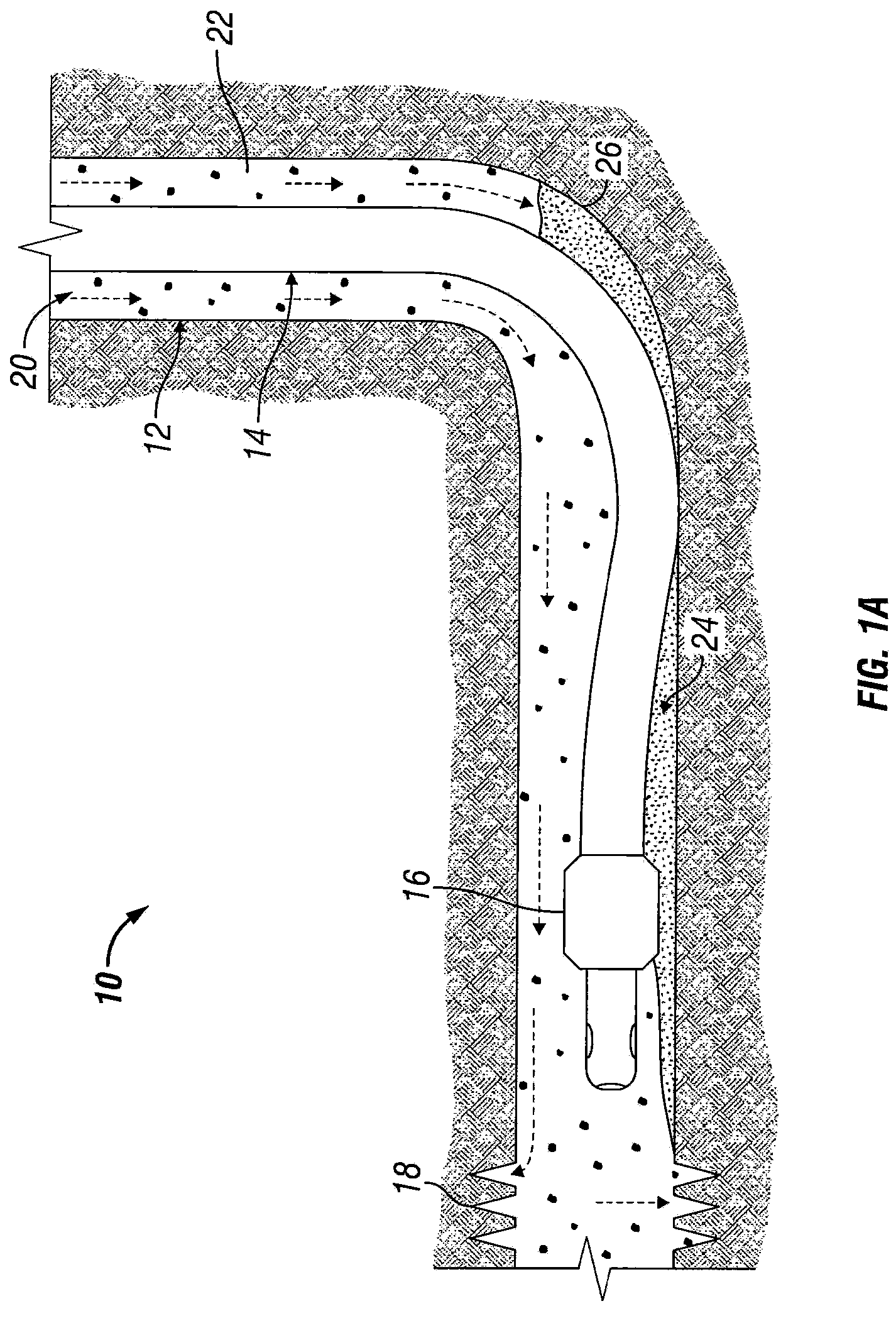
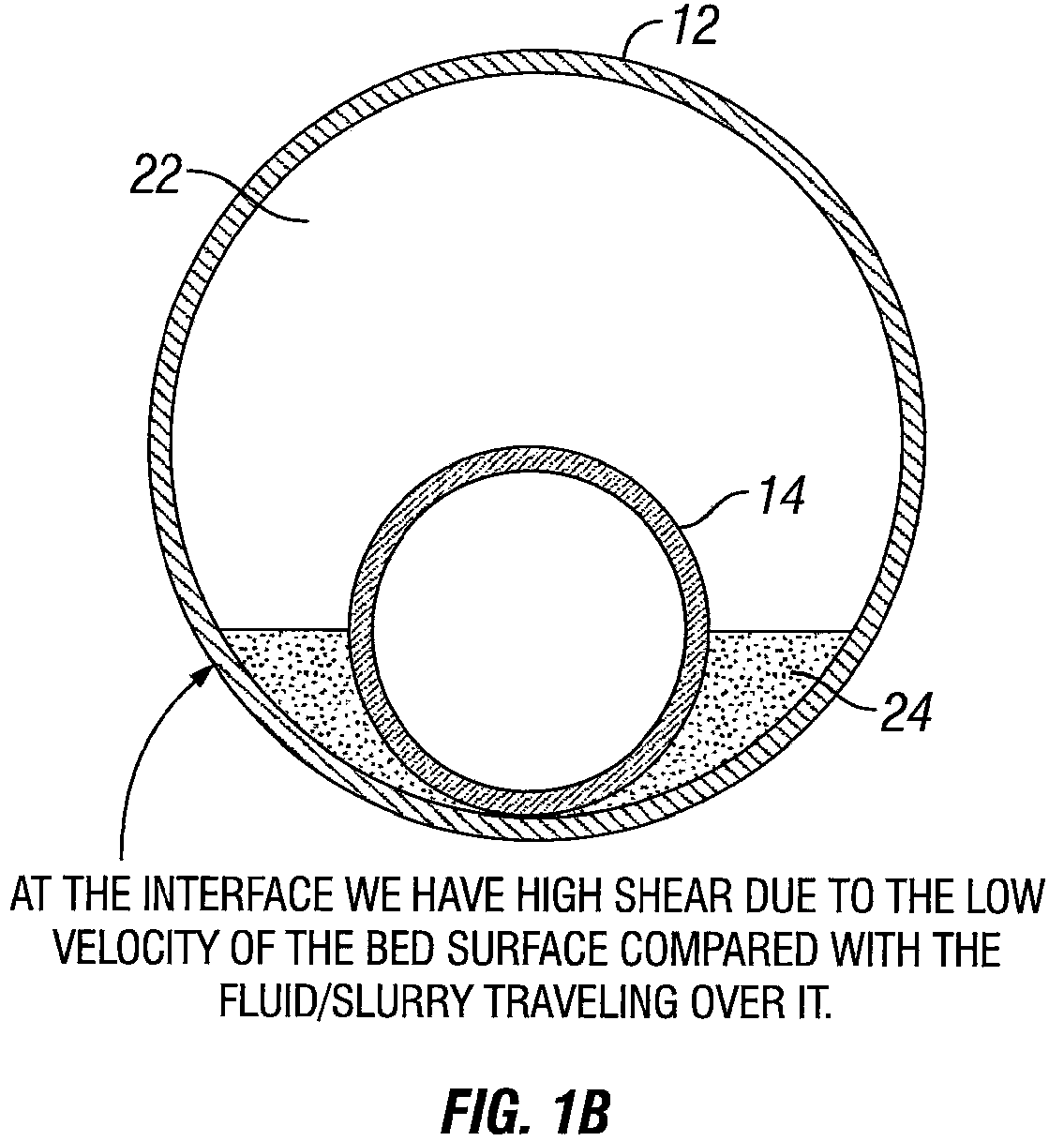
[0030]Referring to FIG. 1A, a horizontal wellbore 10 is illustrated according to an exemplary embodiment of the present invention. For purposes of the present invention, the term “horizontal wellb...


PUM


Abstract

Methods for cleaning out horizontal wellbores using coiled tubing are provided for use during downhole operations. A coiled tubing having a bottom hole assembly is deployed into a horizontal wellbore. Fluid is circulated down the annulus of the wellbore and up the bottom hole assembly while the bottom hole assembly is moved upward at a selected rate and distance. This method may be used to remove downhole solids, such as formation sands and proppant.

Description

BACKGROUND OF THE INVENTION[0001]1. Field of the Invention[0002]The present invention relates generally to wellbore cleanout techniques and, more particularly, to cleaning out horizontal wellbores using coiled tubing.[0003]2. Description of the Related Art[0004]In typical annular coiled tubing fracturing techniques, operators run a bottom hole assembly (“BHA”) in the well with coiled tubing, perforate the casing, pull the bottom hole assembly past the build section into the vertical section of the well or even out of the well entirely, and then begin pumping fracturing fluid. A sand plug is then set as the final stage of the fracture pumping operation, the BHA is run back in hole to a desired location above the previous interval and another interval is perforated. The BHA is then pulled back into the vertical section or out of the well, and fracturing commences again. Accordingly, there are multiple trips in and out of the well. In some instances, the use of mechanical bridge plugs ...

Claims


Application Information

Patent Timeline
Patent Type & Authority Patents(United States)
IPC IPC(8): E21B37/00E21B43/25E21B43/26
CPCE21B37/00E21B43/26
Inventor MISSELBROOK, JOHN GORDONAITKEN, WILLIAM ARTHUR HUTTONLI, JEFF
Owner BAKER HUGHES INC
Learn More