
Method and solar-powered wind plant for producing electric power

Inactive Publication Date: 2012-09-13
ALTERNATIVE ENERGY RES
View PDF88 Cites 4 Cited by
  • Summary
  • Abstract
  • Description
  • Claims
  • Application Information

AI Technical Summary

Benefits of technology

[0054]Besides, together with increase in the efficiency factor and design simplification (lack of blades) additional positive effects of the invention such as considerable reduce in the installation overall dimensions and weight shall be noted. It is possible to yield a capacity of wide range up to very high one by using the plurality of the vertical modules or increasing the ongoing air stream speed. The use of the solar batteries with the solar beam concentrators increases their efficiency. They ensure power supply to the frame drive motor with the wind turbines during day-time.
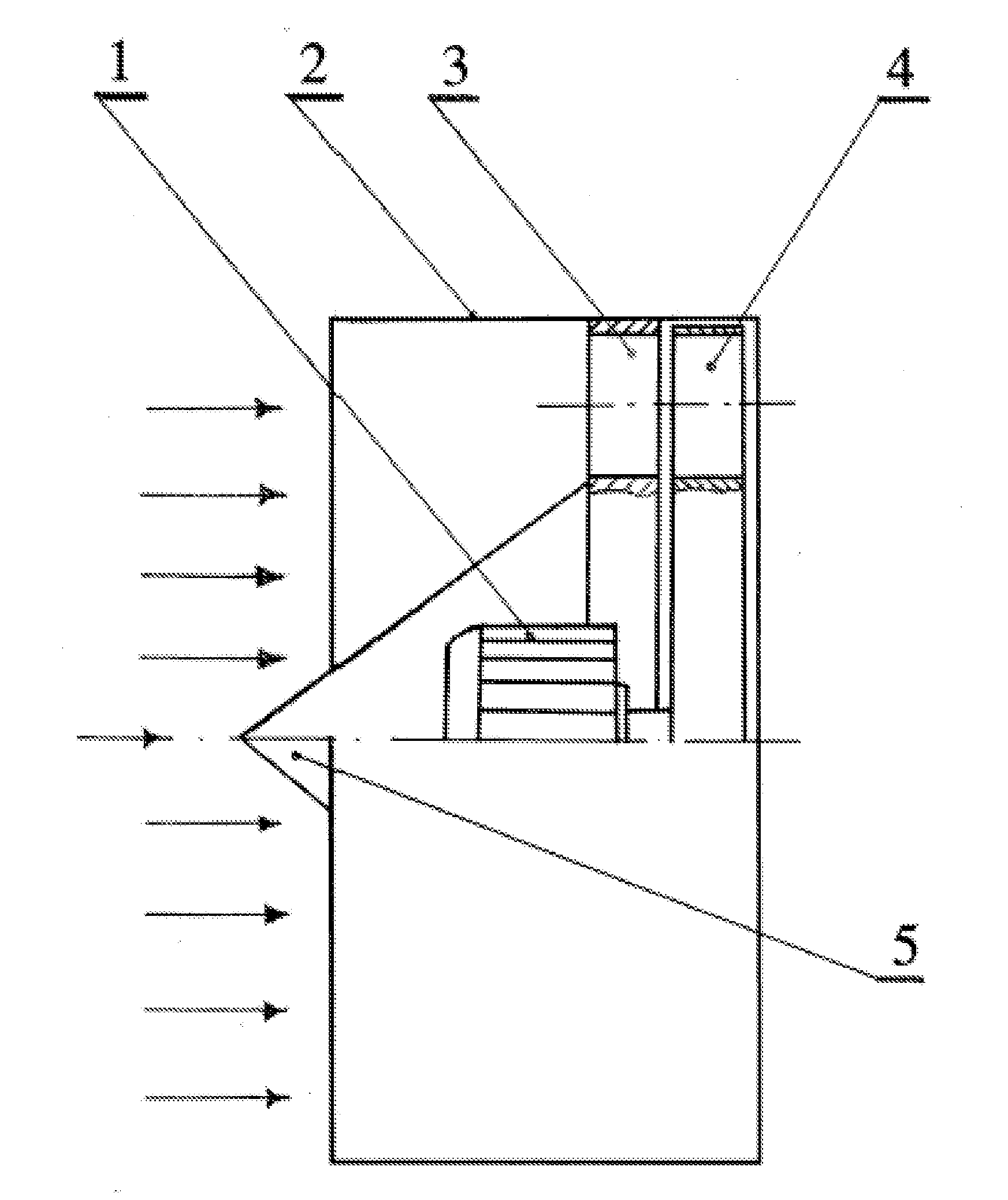
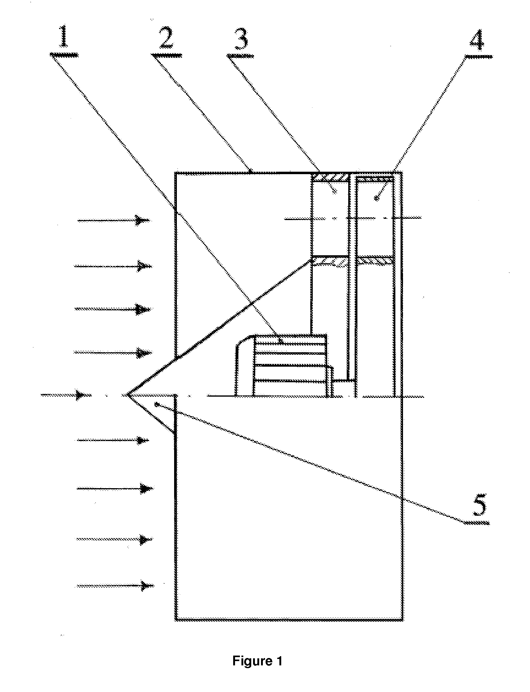
[0055]FIG. 1 shows an example of a turbine and preferable variant for implementing the method and installation for producing electric power by means of rotation of the rotor due to pressure of the ongoing turned wind stream. This variant includes the electric generator 1, annular fairing 2, guiding holes 3 turning the air stream, turbine rotor with inclined holes 4 and cone fairing 5.
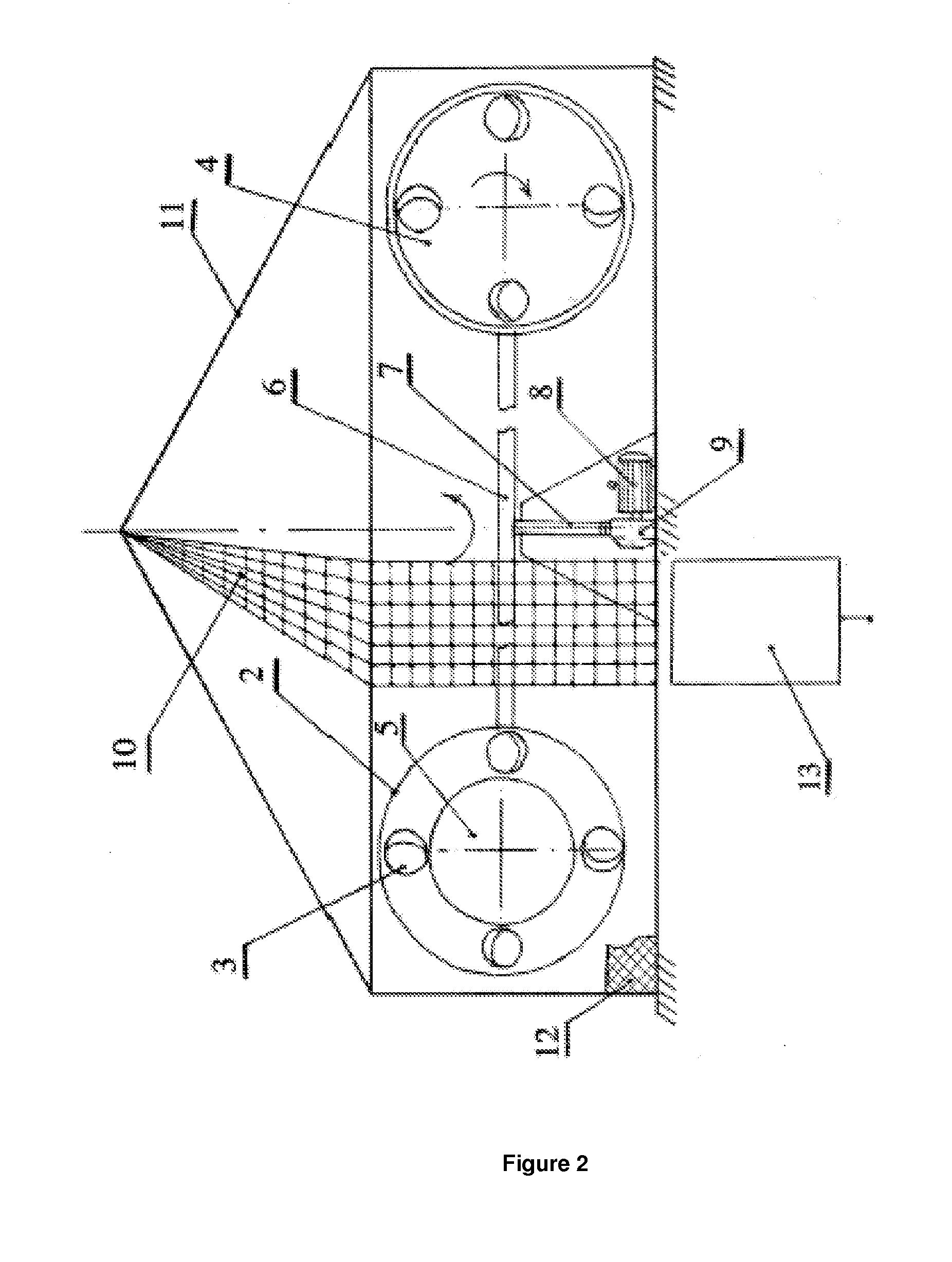
[0056]FIG. 2 shows the diagram of two bladeless turbines installation. The frame 6 is mounted on the movable support base 7. The frame 6 is rotated by the motor (electric motor) 8 through a gear 9. The frame 6 is rotated with a constant speed. The motor 8 is connected to the solar batteries 10. The solar batteries 10 are equipped with the solar beam concentrators 13. The installation is provided with an enclosure 11 and protective screen 12.
[0057]FIG. 3 shows an example of the installation for producing electric power by the proposed turbine and natural wind. The turbine 14 on the rotatable frame 15 is directly mounted on the support base 16.
[0058]The operating principle of the installation utilizing natural wind stream and ongoing air stream is the same. But the air (wind) stream speed shall be not less than 6-8 m / s. The overall dimensions of the proposed installation (at the same capacity) are several times less than ones of conventional blade-type wind plants.
[0059]The given installation is operated as follows. The electric current from the solar battery with mirror concentrators is supplied to the motor 8 which rotates the gear 9. The gear 9 is kinematically connected to the movable support 7 on which the frame 8 is mounted. The turbine rotor with the holes 4 is rotated at the frame (6) ends due to the ongoing air stream of 15 m / s.

Problems solved by technology

During operation such engines burn fuel and negatively affect the ecological environment.
In time, their efficiency is permanently reduced due to the surface contamination of the solar batteries.
At the same time, the solar batteries usually occupy large area and are expensive products.
The drawback of the given wind-powered installation and method for producing electric power is direct wind speed dependence.
As a rule, electric power generation is suspended due to the lack of the required wind stream speed.
Such drawback is inherent to all modern wind plants notwithstanding the wind turbine design.
A need for mounting the wind turbine on the high support secured to the heavy weight concrete plate is seen as another drawback of the wind powered installation in question.
Naturally, such a design increases the project costs and results in vast material consumption.
One more drawback of the said wind plant is the lack of the wind guided blades and annular fairing.
Such deficiency reduces the wind turbine efficiency because the angle at which the air stream impinges on the turbine blades is not optimal.
Due to the said phenomena, the air stream does not produce sufficient mechanic energy at the wind turbine and, hence, its efficiency factor reduces to 30%.

Method used


Image

  • Method and solar-powered wind plant for producing electric power
  • Method and solar-powered wind plant for producing electric power
  • Method and solar-powered wind plant for producing electric power

Examples


example 2

[0065]The installation for producing electric power has been manufactured. The installation includes the generator 1 with a capacity of 1 kW, annular fairing 2 of 350 mm in diameter, cone fairing 5 at an angle of 70°, guiding partition with holes 3 at an angle of 45°. The generators are mounted on the moveable frame 6 on which two power-generating modules (turbines) are installed.

[0066]The rotor and guiding partition have 16 holes each. The power-generating modules have the same weight. The motor 8, frame 6 drives have a capacity of 0.8 kW at 3000 rpm. The gear (9) ratio is 1:50. The rotation radius is two meters. The installation is started up in the same manner as specified in example 1. The solar batteries rotate the frame with a speed of 60 rpm and the ongoing stream speed is approx. 12 m / s. At such a speed of the ongoing stream the vortex turbine and generators operate under the nominal mode. If necessary, one of the generators is switched over to the motor 8, and the second ge...


PUM


Abstract

The invention relates to the field of producing electric power by artificially creating an air stream incident on a power-generating module (turbine) using solar-powered batteries. The power-generating module turns, compresses the air stream and directs the latter onto the working surface of a blade-less rotor. The rotor is designed such that a reactive effect is created on the working surfaces thereof, which improves the turbine characteristics. In the proposed method for producing power, use is made of the kinetic and potential energy of the air stream, and also the moment of inertia of the installation and solar-powered batteries. The efficiency of the method reaches 50%, while traditional fuel is economized on and emissions of CO2 into the atmosphere are reduced.

Description

TECHNICAL FIELD[0001]The invention relates to the field of producing electric power and may be used in power engineering, other industries, and for household purposes. The claimed method and plant do not burn fossil fuels (coil, oil, gas, nuclear fuel, hydrogen) and do not produce any exhaust gases or hazard emissions.BACKGROUND OF THE INVENTION[0002]There are well-known different ways to generate electric power by internal combustion engines, gas turbine engines utilizing the conventional fuels. During operation such engines burn fuel and negatively affect the ecological environment. It is known that electric power may be also generated by conversing solar energy. However, efficiency of solar batteries, e.g. US E19 / 318, amounts to 19.5%. In time, their efficiency is permanently reduced due to the surface contamination of the solar batteries. At the same time, the solar batteries usually occupy large area and are expensive products. Notwithstanding these drawbacks the solar batterie...

Claims


Application Information

Patent Timeline
IPC IPC(8): H02J5/00
CPCF03D1/04Y02E10/721F03D9/007F03D1/06Y02E10/72Y02E70/30F03D9/11
Inventor URSU, ION GEORGIEVICHPOTAPOV, YURIY SEMENOVICH
Owner ALTERNATIVE ENERGY RES
Learn More