Rear gun sight device for AK47 or similar rifle

a rear gun and sight device technology, applied in the field of rear gun sight devices for rifles, can solve the problems of increased sight radius, short sight radius, large inaccuracy when engaging the intended target, etc., and achieve the effect of short sight radius, improved sight, and increased sight radius

Active Publication Date: 2011-02-08
NESSETH LAWRENCE ARDEN +1
View PDF2 Cites 5 Cited by
  • Summary
  • Abstract
  • Description
  • Claims
  • Application Information

AI Technical Summary

Benefits of technology

[0006]This invention relates generally to the field of rear guns sight devices for rifles and more specifically to a rear gun sight device for a rifle having a receiver and cover, the receiver having a tee shaped slot on the top rear of the receiver. This slot is designed to accept and retain a recoil assembly. The invention replaces the rear portion of the recoil assembly. This allows the invention to perform the function of the original rear portion of the recoil assembly as well as provide a rear sight for the rifle. The novel rear gun sight device is especially adapted to the AK47 or similar type rifle. This rear gun sight device includes a sight base with a tee shaped base that engages the tee shaped slot in the rear portion of the AK47 receiver providing a stable base for the sight assembly to mount. By integrating the rear gun sight device into the recoil system of the AK47 rifle the rear gun sight device is able to utilize this tee shaped slot without restricting the function of the AK47's operating system. This invention provides the AK47 with an improved sight by increasing the sight radius by approximately eight inches. The original AK47 sight is of a tangent type and is mounted on the barrel ahead of the receiver, resulting in a very short sight radius. The shorter sight radius provided for in the original design of the rifle is more likely to cause human error when aligning sights to engage a target.
[0007]In accordance with a preferred embodiment of the invention, there is disclosed a rear gun sight device for a rifle having a receiver and cover, the receiver having a tee shaped slot on the top rear of the receiver. This slot is designed to accept and retain a recoil assembly. The invention replaces the rear portion of the recoil assembly. This allows the invention to perform the function of the original rear portion of the recoil assembly as well as provide a rear sight for the rifle. The rear gun sight device is comprised of a sight base with an integrated tee shaped base to engage the tee shaped slot in the top rear trunion of the rifle's receiver, a spring boss to accept the end of the recoil spring when assembled in the recoil assembly, a spring guide to guide the recoil spring, cover retention elements and sight component assembly comprised of windage and elevation adjustment components as well as sight elements attached directly to the sight base.
[0008]In accordance with a preferred embodiment of the invention, there is disclosed a rear gun sight device for a rifle having a receiver and cover, the receiver having a tee shaped slot on the top rear of the receiver. This slot is designed to accept and retain a recoil assembly. The invention replaces the rear portion of the recoil assembly. This allows the invention to perform the function of the original rear portion of the recoil assembly as well as provide a rear sight for the rifle. The rear gun sight device is comprised of a sight base with an integrated tee shaped base to engage the tee shaped slot in the top rear trunion of the rifle's receiver, a spring boss to accept the end of the recoil spring when assembled in the recoil assembly, a spring guide to guide the recoil spring, cover retention elements and sight component subassembly comprised of windage and elevation adjustment components as well as sight elements. This sight component subassembly is attached to the sight base by various means such as but not limited to screws, clamping or friction.OBJECTS OF THE INVENTION

Problems solved by technology

This results in a very short sight radius.
Any misalignment of the front and rear sights using the short sight radius provided on the AK47 in it's original configuration results in large inaccuracies when engaging the intended target.
This increased the sight radius, but was mounted to the receiver cover which is unstable for precision mounting a rear sight.

Method used


Image

  • Rear gun sight device for AK47 or similar rifle
  • Rear gun sight device for AK47 or similar rifle
  • Rear gun sight device for AK47 or similar rifle

Examples


Embodiment Construction

[0031]Detailed descriptions of the preferred embodiment are provided herein. It is to be understood, however, that the present invention may be embodied in various forms. Therefore, specific details disclosed herein are not to be interpreted as limiting, but rather as a basis for the claims and as a representative basis for teaching one skilled in the art to employ the present invention in virtually any appropriately detailed system, structure or manner.

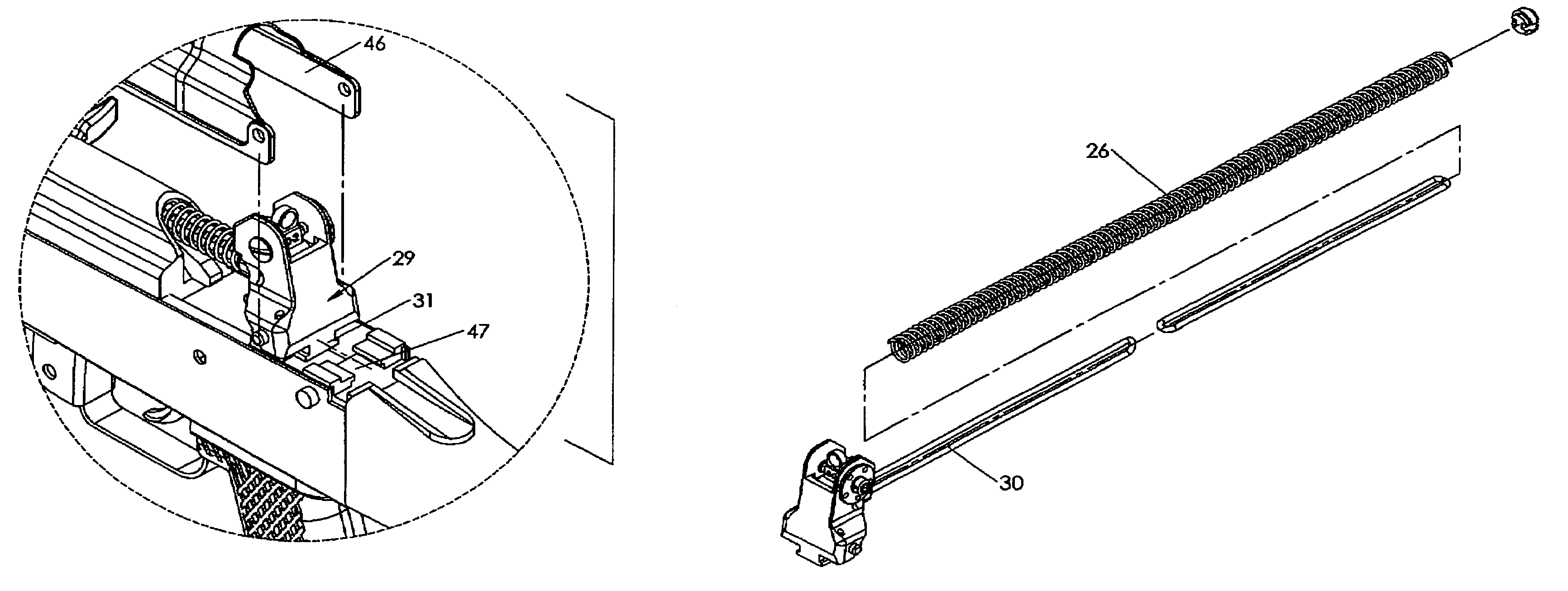
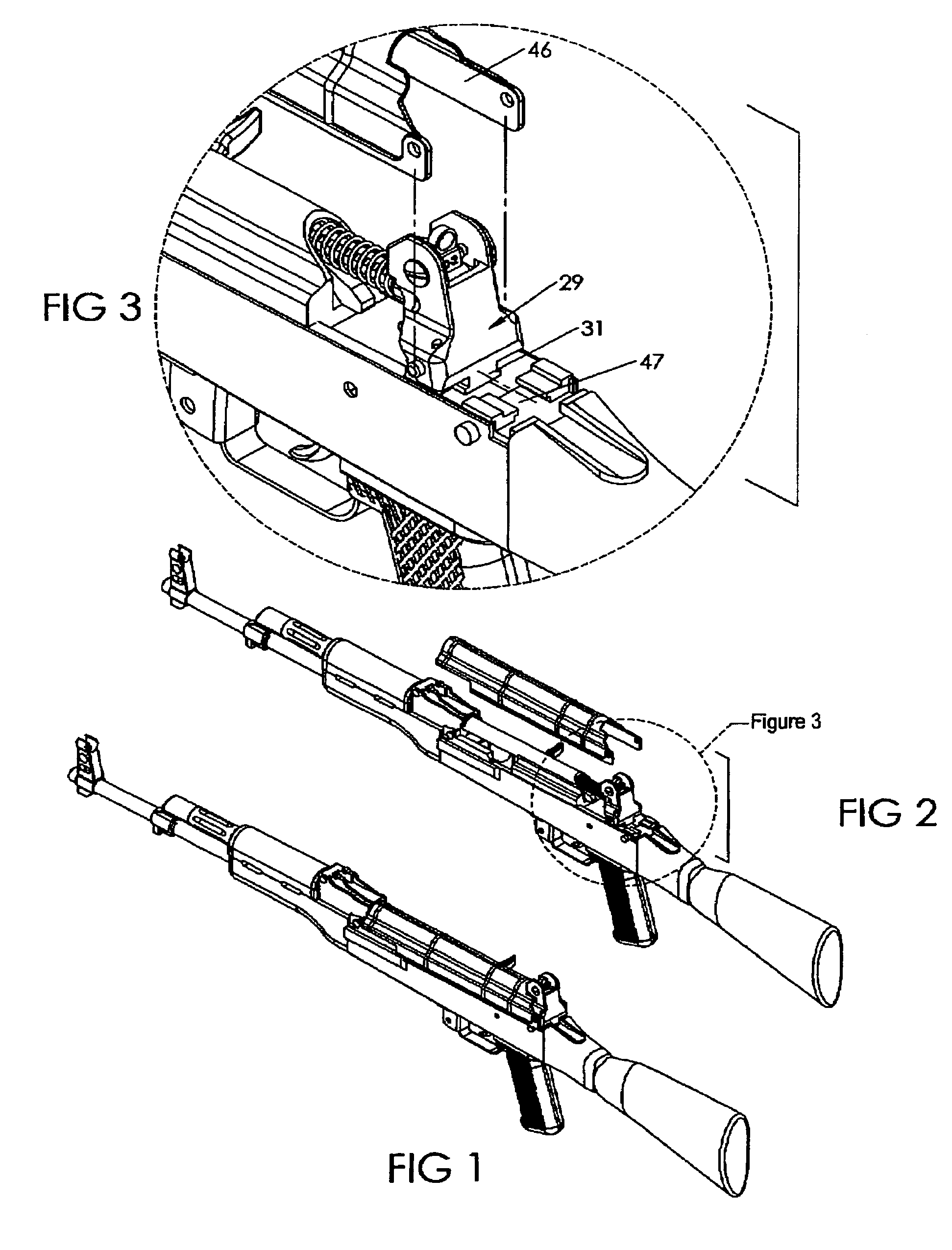
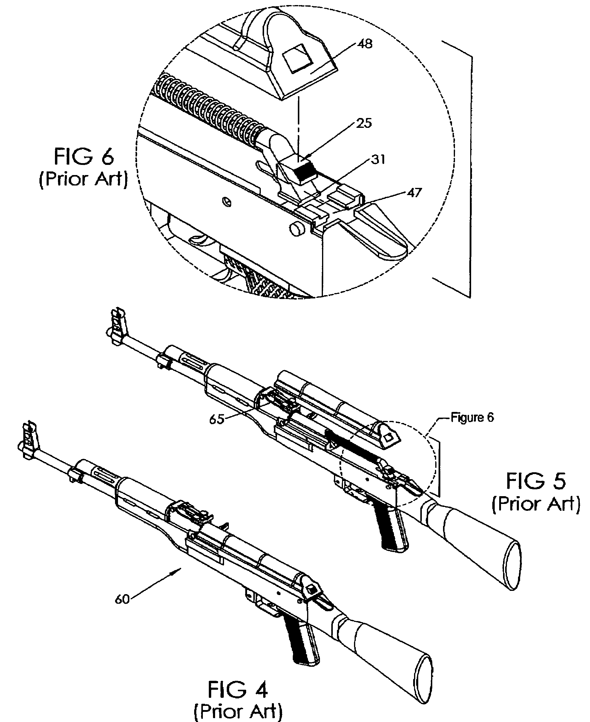
[0032]The present invention is a rear gun sight device 30 as shown in FIG. 16 for the AK47 or similar rifle 60 as depicted in FIG. 4, which is comprised of the following elements: a sight base 21 with integrated tee shaped base 31 as depicted in FIG. 12, a sight component assembly 22, a spring guide 33 and receiver cover retention features 40 as shown in FIG. 16. This rear gun sight device will also be referred to as guide rod with integrated sight 30 in this detailed description of the preferred embodiments. The guide rod with integ...


PUM


Abstract

A rear gun sight device for a rifle having a receiver and cover, the receiver having a tee shaped slot on the top rear of the receiver. This slot is designed to accept and retain a recoil assembly. The invention replaces the rear portion of the recoil assembly allowing the invention to perform the function of the original rear portion of the recoil assembly as well as provide a rear sight for the rifle. This invention is comprised of a sight base provided with a tee shaped base to engage the tee shaped slot in the top rear trunion of the rifle's receiver, a spring boss to accept the end of the recoil spring when assembled in the recoil assembly, a spring guide to guide the recoil spring, a sight component assembly comprised of windage and elevation adjustment components as well as aperture sight components, and cover retention elements.

Description

CROSS REFERENCE TO RELATED APPLICATIONS[0001]Not applicable.STATEMENT REGARDING FEDERALLY SPONSORED RESEARCH OR DEVELOPMENT[0002]Not ApplicableDESCRIPTION OF ATTACHED APPENDIX[0003]Not ApplicableFIELD OF THE INVENTION[0004]This invention relates generally to the field of rear guns sight devices for rifles and more specifically to a rear gun sight device for a rifle having a receiver and cover, the receiver having a tee shaped slot on the top rear of the receiver.BACKGROUND OF THE INVENTION[0005]The AK47 rifle in its original configuration is equipped with a tangent notch sight mounted just forward of the rifles receiver approximately 10″ from the shooters eye. This results in a very short sight radius. Any misalignment of the front and rear sights using the short sight radius provided on the AK47 in it's original configuration results in large inaccuracies when engaging the intended target. One method of increasing the sight radius on a AK47 type rifle was employed by Israel Militar...

Claims


Application Information

Patent Timeline
Patent Type & Authority Patents(United States)
IPC IPC(8): F41G1/38
CPCF41G1/12
Inventor NESSETH, LAWRENCE ARDENNESSETH, ERIK LAWRENCE
Owner NESSETH LAWRENCE ARDEN
Why Eureka
Try Eureka