Gas eduction tube for seabed caisson pump assembly

a technology of gas eduction tube and pump assembly, which is applied in the direction of special purpose vessels, separation processes, and well accessories, etc., can solve the problems of gas present a problem for pumps, gas detracts from pump efficiency, and the fluid cannot be flown thousands of feet upwards

Inactive Publication Date: 2011-02-08
BAKER HUGHES INC
View PDF28 Cites 21 Cited by
  • Summary
  • Abstract
  • Description
  • Claims
  • Application Information

AI Technical Summary

Problems solved by technology

The wells may have adequate pressure to flow the well fluid to the seabed, but lack sufficient pressure to flow the fluid thousands of feet upward to a production vessel.
Gas presents a problem for pumps, particularly electrically driven centrifugal pumps.
Gas detracts from the efficiency of the pump, and can cause the pump to lock and shut down if a large slug of gas enters.
A possibility exists that the gas cap will grow and push the liquid level too low, resulting in a large quantity of the gas entering the pump and causing it to gas lock.
A large gas slug could nevertheless still enter the pump and cause a gas lock.

Method used


Image

  • Gas eduction tube for seabed caisson pump assembly
  • Gas eduction tube for seabed caisson pump assembly
  • Gas eduction tube for seabed caisson pump assembly

Examples


Embodiment Construction

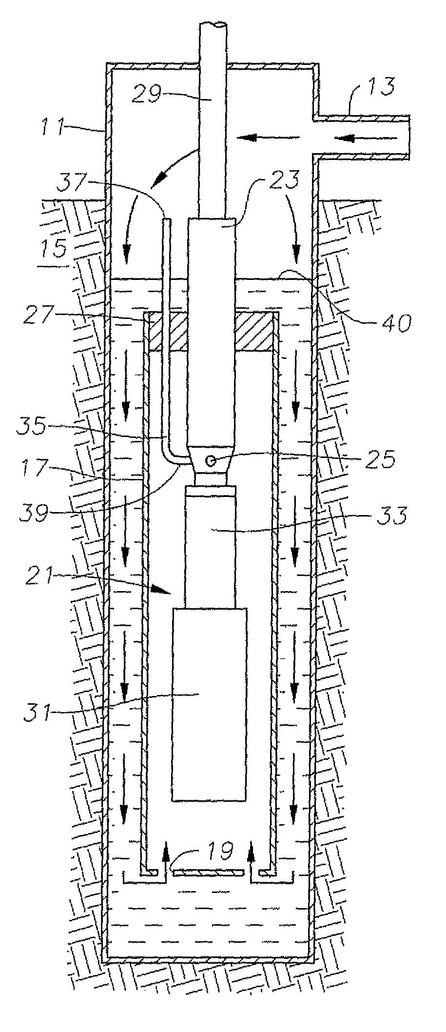
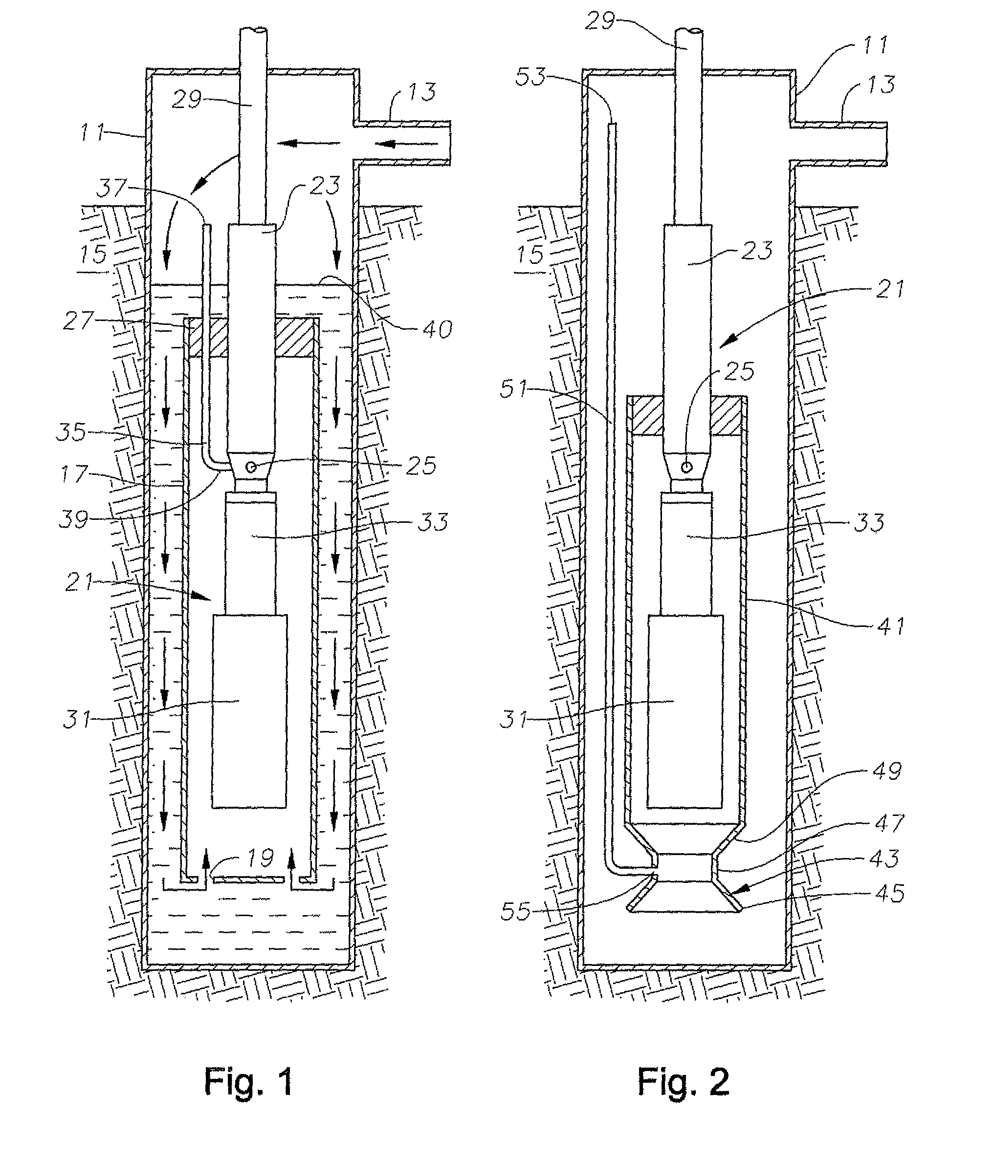
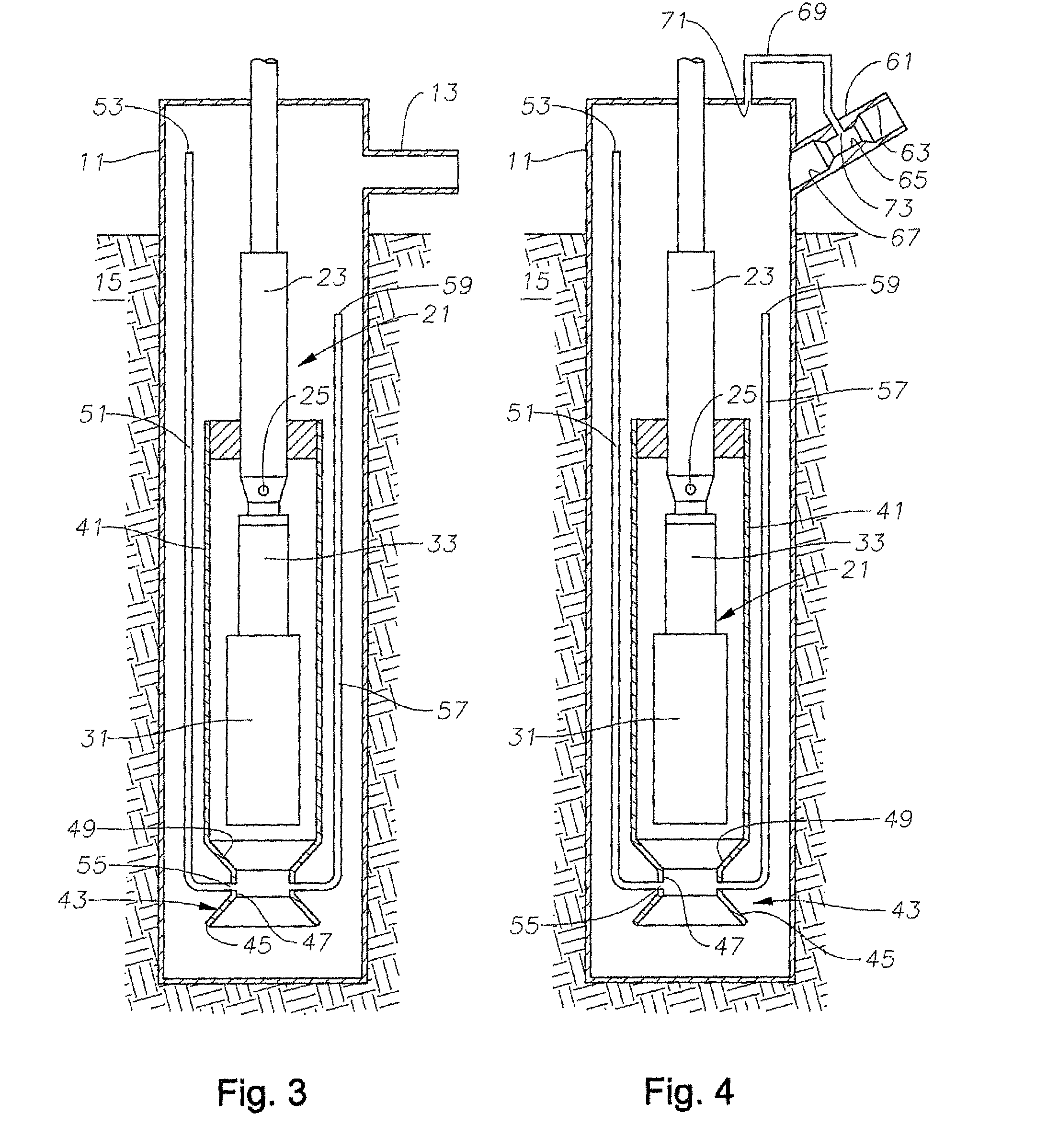
[0012]Referring to FIG. 1, a caisson 11 is shown schematically. Caisson 11 comprises a hole that has been formed in the seafloor to a desired depth, which may be several hundred feet. Caisson 11 is encased in a casing that is impermeable to any fluids from earth formation 15. Caisson 11 has an inlet 13 that is located near its upper end, such as slightly above the seabed.

[0013]A shroud 17 is located within caisson 11. Shroud 17 has an inlet 19 at its lower end, Shroud 17 is a tubular member that is smaller in diameter than the inner diameter of caisson 11 so as to create an annular passage surrounding it for downward fluid flow.

[0014]An electrical submersible pump assembly (“ESP”) 21 is mounted within shroud 17. ESP 21 has a pump 23 that is typically a centrifugal pump. Pump 23 is made up of a large number of stages, each having a rotating impeller and a stationary diffuser. Pump 23 has an intake 25 that is located at the lower end of pump 23 within shroud 17. Shroud 17 has an upper...


PUM

PropertyMeasurementUnit
depthaaaaaaaaaa
diameteraaaaaaaaaa
flow areaaaaaaaaaaa

Abstract

A seafloor pump assembly is installed within a caisson that has an upper end for receiving a flow of fluid containing gas and liquid. The pump assembly is enclosed within a shroud that has an upper end that seals around the pump assembly and a lower end that is below the motor and is open. An eduction tube has an upper end above the shroud within the upper portion of the caisson and a lower end in fluid communication with an interior portion of the shroud. The eduction tube causes gas that separates from the liquid and collects in the upper portion of the caisson to be drawn into the pump and mixed with the liquid as the liquid is being pumped.

Description

FIELD OF THE INVENTION[0001]This invention relates in general to pumping well fluid from the seabed to the surface, and in particular to a pump assembly located within a caisson and having an eduction tube to reduce gas accumulation in the caisson.BACKGROUND OF THE INVENTION[0002]Offshore wells are being drilled in increasingly deeper waters. The wells may have adequate pressure to flow the well fluid to the seabed, but lack sufficient pressure to flow the fluid thousands of feet upward to a production vessel. Proposals have been made to install pumps at the seabed to boost the pressure of the well fluid sufficiently to flow it to the floating production vessel.[0003]Often, the well fluid will be a mixture of hydrocarbon liquid, gas and water. Gas presents a problem for pumps, particularly electrically driven centrifugal pumps. Gas detracts from the efficiency of the pump, and can cause the pump to lock and shut down if a large slug of gas enters.[0004]One proposal for dealing with ...

Claims


Application Information

Patent Timeline
Patent Type & Authority Patents(United States)
IPC IPC(8): E21B43/01
CPCE21B43/01
Inventor WILSON, BROWN LYLESHAW, CHRISTOPHER K.
Owner BAKER HUGHES INC
Why Eureka
Try Eureka