Heat pump type water heater

a technology of hot water heater and heat pump, which is applied in the direction of heating types, defrosting, domestic cooling devices, etc., can solve the problems of capacity drop, achieve stable boiling-up operation, short activation time, and avoid capacity drop.

Inactive Publication Date: 2011-02-08
DAIKIN IND LTD
View PDF39 Cites 17 Cited by
  • Summary
  • Abstract
  • Description
  • Claims
  • Application Information

AI Technical Summary

Problems solved by technology

Accordingly, in some cases where the outside air temperature is low, frost formation may occur on the air heat exchanger 78, resulting in a drop in capacity.

Method used


Image

  • Heat pump type water heater
  • Heat pump type water heater
  • Heat pump type water heater

Examples


Embodiment Construction

[0031]A specific embodiment of a heat pump type hot water supply apparatus in accordance with the present invention will be described in detail with reference to the drawings.

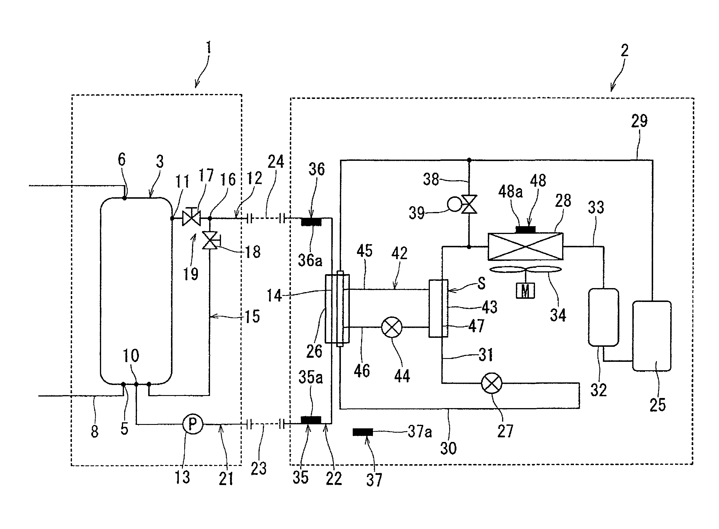
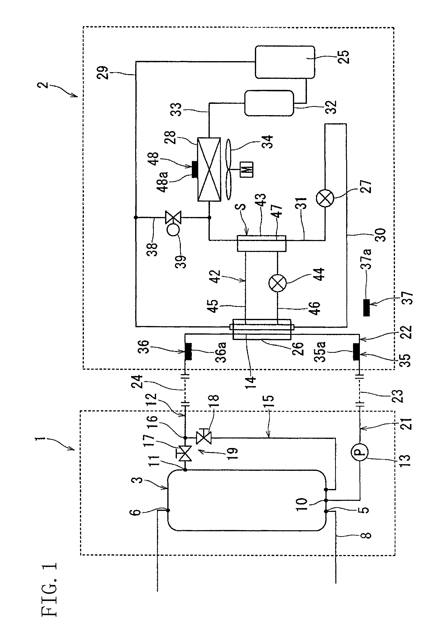
[0032]Referring to FIG. 1, there is shown a simplified diagram of the heat pump type hot water supply apparatus. The heat pump type hot water supply apparatus is comprised of a hot water supply cycle 1 and a refrigerant cycle 2. The hot water supply cycle 1 includes a hot water storage tank 3, wherein hot water stored in the hot water storage tank 3 is supplied to a bathtub (not shown in the figure) or the like. More specifically, the hot water storage tank 3 is provided, at its bottom wall portion, with a water supply opening 5 and is further provided, at its top wall portion, with a hot water supply opening 6. And, tap water is supplied to the hot water storage tank 3 from the water supply opening 5 and high-temperature hot water is delivered outwardly from the hot water supply opening 6.

[0033]In addition, in...


PUM


Abstract

A hot water storage tank (3) and a circulating path (12) coupled to the hot water storage tank (3) are provided. An operation is possible wherein low-temperature water, let out from a lower part of the hot water storage tank (3) and entering the circulating path (12), is heated and boiled up by a heat pump heating source for forwarding to an upper part of the hot water storage tank (3). A refrigerant circulating circuit of the heat pump heating source is provided with a defrost circuit (38) for supplying hot gas from a compressor (25) to an air heat exchanger (28). It is possible to perform a defrost operation for providing a supply of hot gas to the air heat exchanger (28), with a water circulation pump (13) of the circulating path (12) held in abeyance. The water circulation pump (13) is made active if the defrost operation has been continued for not less than a predetermined time period since the start thereof.

Description

TECHNICAL FIELD[0001]This invention relates to a heat pump type hot water supply apparatus.BACKGROUND ART[0002]Referring to FIG. 8, there is shown a heat pump type hot water supply apparatus having a refrigerant cycle 72 and a hot water supply cycle 71. The refrigerant cycle 72 includes a compressor 74, a hot water supply heat exchanger (utilization side heat exchanger) 75, an electric expansion valve 77, and a heat source side heat exchanger (air heat exchanger) 78 which are all connected in the given order. On the other hand, the hot water supply cycle 71 includes a hot water storage tank (hot water supply tank) 70 and a circulating path 79. A water circulation pump 80 and a heat exchanging path 81 are inserted in the circulating path 79. In this case, the heat exchanging path 81 is formed by the utilization side heat exchanger (water heat exchanger) 75.[0003]In the above-described heat pump type hot water supply apparatus, when the compressor 74 is activated while the pump 80 is ...

Claims


Application Information

Patent Timeline
Patent Type & Authority Patents(United States)
IPC IPC(8): F24D11/02F24H1/00F24D19/10F24H4/04F25B1/00F25B9/00F25B30/02F25B40/00F25B47/02
CPCF24D19/1039F24D19/1054F24H4/04F25B30/02F25B40/00F25B47/02F25B47/022F25B9/008F25B2309/061F25B2339/047F25B2600/0253F25B2600/2501F25B2700/2106Y02B30/741Y02B30/70F24H15/38F24H15/136F24H15/414F24H15/385F24H15/258F24H15/215F24H15/375F24H15/325F24H15/219F24H15/335F24H15/486
Inventor NAKAYAMA, HIROSHISAKAMOTO, SHINICHI
Owner DAIKIN IND LTD
Why Eureka
Try Eureka