Device for influencing the movement of furniture parts which can be moved with respect to one another, and piece of furniture

a technology for moving parts and furniture, applied in the field of devices, can solve the problems of requiring intensive maintenance, prone to defects, and relatively complex production, and achieve the effects of simple installation, simple compensation, and compact design

Inactive Publication Date: 2011-02-08
GRASS GMBH
View PDF18 Cites 16 Cited by
  • Summary
  • Abstract
  • Description
  • Claims
  • Application Information

AI Technical Summary

Benefits of technology

[0005]The object of the present invention is to provide a device for the movement of furniture parts which can be moved relative to one another, and to provide a piece of furniture having a device such as this, in particular with the aim of the device having a particularly compact design and being simple to install, and making it simple to compensate for the discrepancies which occur from an ideal installation situation for the device.
[0006]First of all, the invention is based on a device for influencing the movement of furniture parts which can be moved with respect to one another, having a guide unit for guidance of a first furniture part on a second furniture part, and having a drive unit by means of which the first furniture part can be moved, in a driven manner, relative to the second furniture part. The guide unit has a fixed rail, which is associated with the second furniture part, and a moving rail, which is associated with the first furniture part. One major aspect of the invention is that a pulling-pushing element is provided in order to apply a drive effect from the drive unit to the first furniture part, guided on the fixed rail via guide means. A pulling-pushing element which can be moved by the drive unit makes it possible to produce a device for influencing the movement of furniture parts which can be moved relative to one another, for the driven movement of at least one furniture part, in a comparatively very compact and space-saving manner. In particular, the pulling-pushing element results in a simple transmission means, which operates particularly reliably, for a to-and-fro movement. Furthermore, virtually all movement patterns of furniture parts which can be moved relative to one another can advantageously be carried out by a to-and-fro movement of a transmission element. In this case, it is particularly advantageous that a pulling-pushing element can transmit both relatively very high pushing and pulling forces, even over considerable distances, translationally and in the direction of its longitudinal extent. If required, the pulling-pushing element may be flexible or bendable, at least over sub-sections. This may be advantageous with respect to spatial orientations which have to be set up differently and / or for transmission of the drive effect in different directions, and for the necessary space requirement for the pulling-pushing element. In particular, the comparatively slimline pulling-pushing element makes it possible to dispense with complex devices for switching and / or deflection of the transmission means.
[0007]The guide means allow the guidance for the pulling-pushing element to be designed to be comparatively simple and space-saving, advantageously making use of the fixed rail which is provided in any case. This is advantageous with regard to the device for influencing movement being designed to be as lightweight and slim as possible. In addition, this means that there is no need to modify the moving rail for the guidance of the pulling-pushing element. At the end, the pulling-pushing element is firmly fitted to the position member, by means of the part which projects out of the guide. The pulling-pushing element is thus accommodated in the guide on the fixed rail, and therefore most of the time in a space-saving manner, when the movable furniture part is in the closed or moved-in position. In principle, guide means can also be provided for guidance of the pulling-pushing element on the moving rail.

Problems solved by technology

An arrangement such as this requires a comparatively large amount of physical space, is relatively complex to produce and, furthermore, requires intensive maintenance and is susceptible to defects.

Method used


Image

  • Device for influencing the movement of furniture parts which can be moved with respect to one another, and piece of furniture
  • Device for influencing the movement of furniture parts which can be moved with respect to one another, and piece of furniture
  • Device for influencing the movement of furniture parts which can be moved with respect to one another, and piece of furniture

Examples


Embodiment Construction

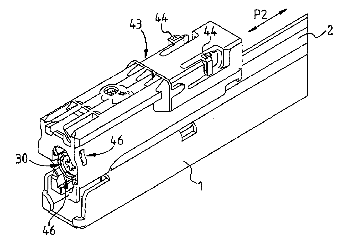
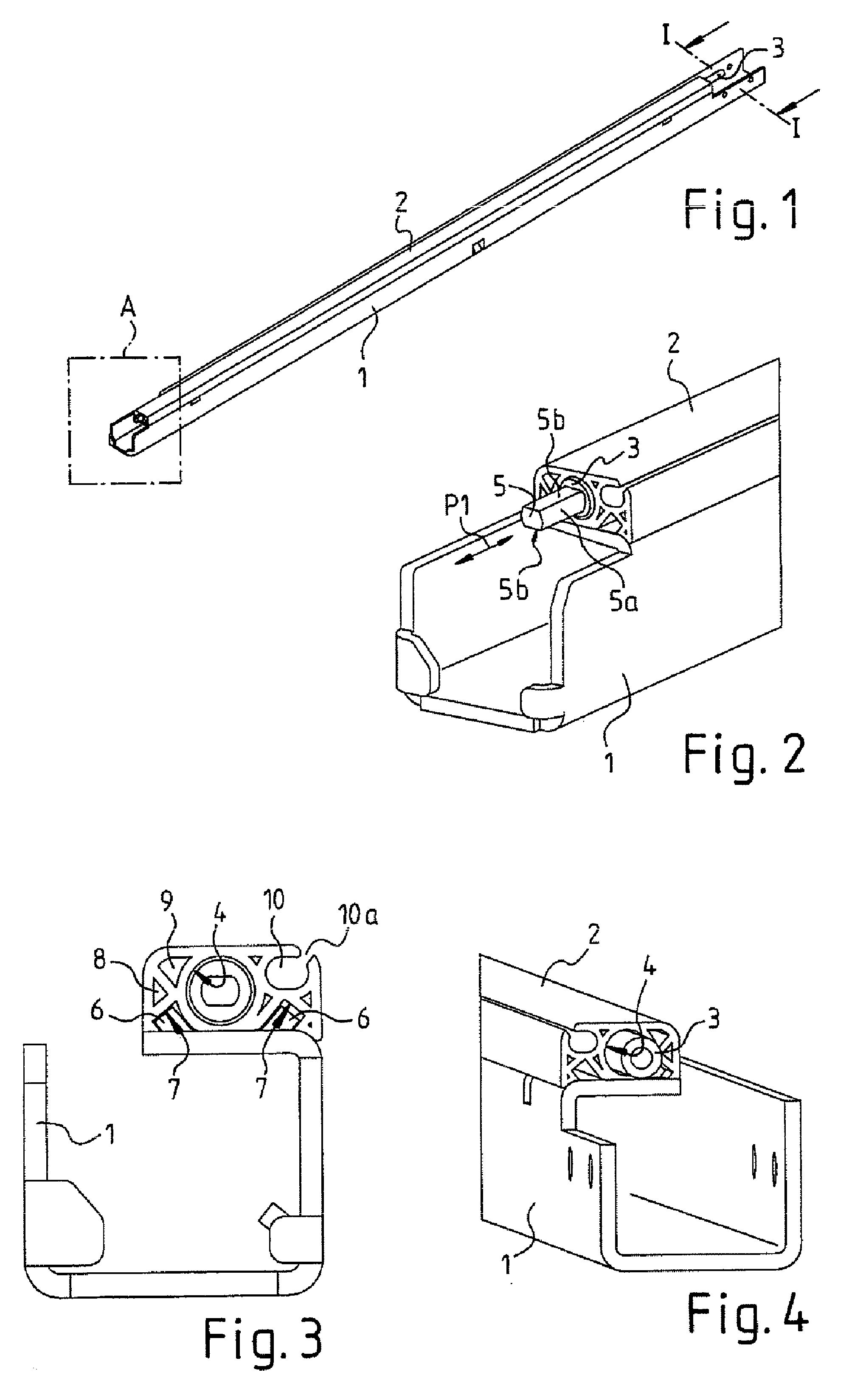
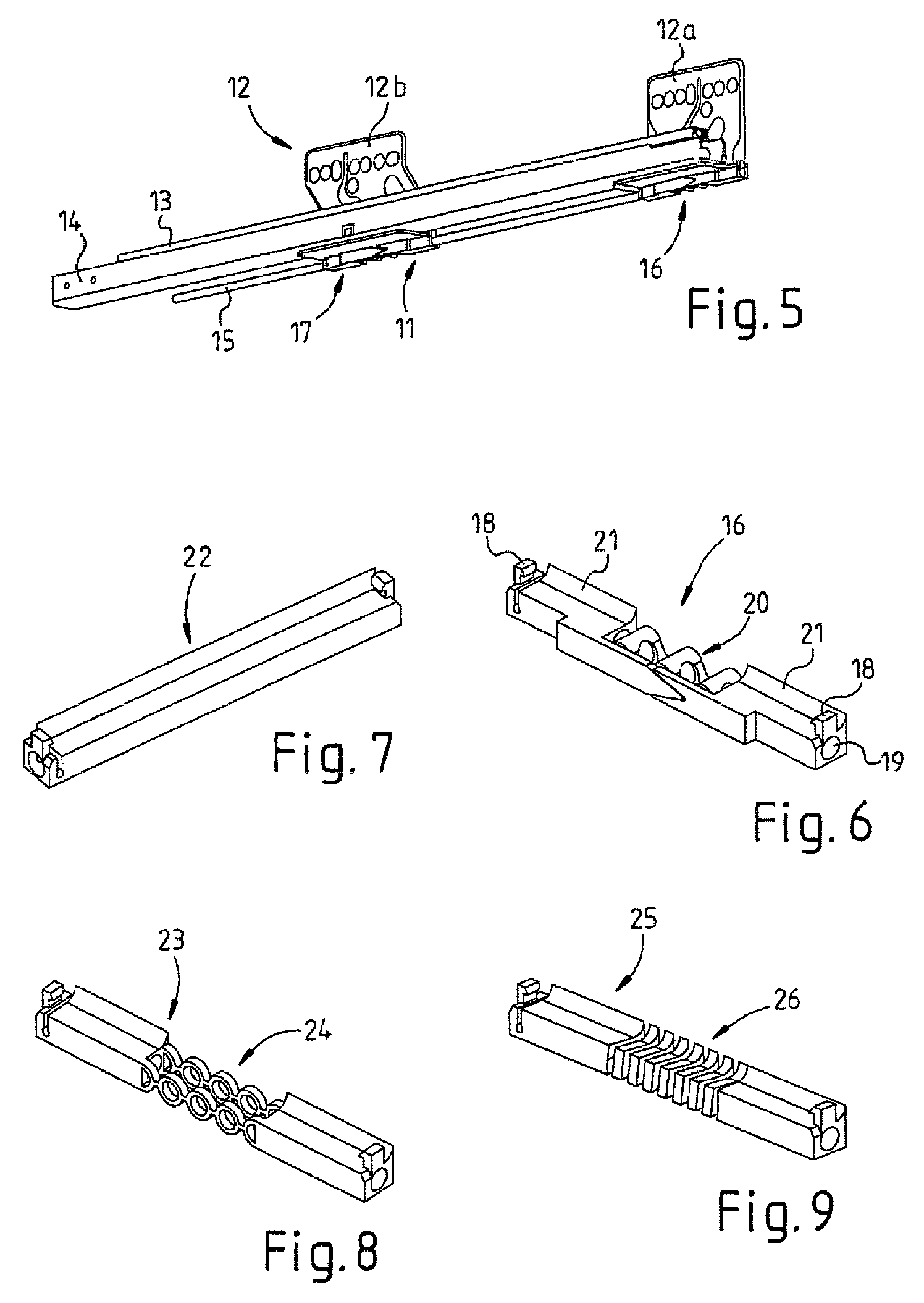
[0052]FIG. 1 shows a base-rail part 1, which comprises a bent-around sheet-metal section, for a housing rail, which is known per se, of a drawer guide. A drawer guide such as this comprises, in particular, a right-hand and a left-hand drawer guide unit, each having a drawer rail which is attached to a drawer and having a housing rail which is firmly fitted to a housing, possibly with a center rail arranged in between.

[0053]When the base-rail part 1 is in the installed position, a guide profile 2 is fitted to it at the top, in which a movement rod 3 of a pulling-pushing element is accommodated. This movement rod 3 may, for example, be a push rod composed of a cylindrical hollow material, in particular composed of metal or plastic. The movement rod 3 is held in a cylindrical elongated hole 4 such that it can move in the longitudinal direction of the movement rod 3 or translationally, or is guided in the form of a journal bearing. A comparatively narrow separating gap can be provided f...


PUM


Abstract

The invention relates to a piece of furniture and to a device for influencing the movement of furniture parts which can be moved with respect to one another, having a guide unit for guidance of a first furniture part on a second furniture part, and having a drive unit to move the first furniture part in a driven manner relative to the second furniture part, with the guide unit having a fixed rail, which is associated with the second furniture part, and a moving rail, which is associated with the first furniture part. A pulling-pushing element is provided in order to apply a drive effect from the drive unit to the first furniture part, guided on the fixed rail via guide means.

Description

CROSS REFERENCE TO RELATED APPLICATIONS[0001]This application is a continuation of International Application No. PCT / EP2007 / 002509, filed Mar. 21, 2007, which designated the United States, and claims the benefit under 35 USC §119(a)-(d) of German Application No. 20 2006 004 718.2 filed Mar. 22, 2006, the entireties of which are incorporated herein by reference.FIELD OF THE INVENTION[0002]The invention relates to a device for influencing the movement of furniture parts which can be moved with respect to one another, and to a piece of furniture.BACKGROUND OF THE INVENTION[0003]Devices are already known for influencing furniture parts which can be moved with respect to one another and can be moved, in a driven manner, relative to one another with the aid of a guide unit and with respect to one another by means of a drive unit. By way of example, toothed belts which revolve between two toothed wheels which are spaced from one another are used to transmit a drive effect from the drive un...

Claims


Application Information

Patent Timeline
Patent Type & Authority Patents(United States)
IPC IPC(8): A47B88/04
CPCA47B88/0414A47B88/0477A47B2210/0078A47B88/457A47B88/463
Inventor LANGGUTH, PETERNUSSBAUMER, THOMASBLUECHER, MARTIN
Owner GRASS GMBH
Why Eureka
Try Eureka