Steering device of vehicle

a steering device and vehicle technology, applied in the direction of non-deflectable wheel steering, process and machine control, underwater equipment, etc., can solve the problems of reduced directional stability of the vehicle, driver may feel strangeness, etc., and achieve the effect of reducing the operation load when the driver operates the steering wheel

Active Publication Date: 2011-02-08
TOYOTA JIDOSHA KK
View PDF16 Cites 8 Cited by
  • Summary
  • Abstract
  • Description
  • Claims
  • Application Information

AI Technical Summary

Benefits of technology

[0016]According to this invention, the transfer function setting means can set the second transfer function, which second transfer function having as an input the target turning rate and as an output the turning amount of the wheels to be turned which are turned at the target turning rate, by the first transfer function determined on the basis of the specification of the vehicle (a vehicle model), which first transfer function having as an input the turning amount of the wheels to be turned and as an output the motion condition amount generated in the vehicle. Further, the correction turning amount calculation means can calculate the correction turning amount by using the second transfer function set as explained above and the target turning rate (in particular, by multiplying the second transfer function by the target turning rate). Thereby, the correction turning amount is calculated in a reflection of (in consideration of) the change of the motion condition amount generated in the vehicle along with the turning of the wheels to be turned, that is, in a reflection of (in consideration of) the frequency responsiveness property. Further, the final target turning amount calculation means can calculate the final target turning amount by adding the correction turning amount to the target turning amount and the turning control means can turn the wheels to be turned by the final target turning amount.
[0028]According to these inventions, the target turning amount calculation means can change the target turning amount of the wheels to be turned relative to the operation input value of the driver to the steering wheel, depending on the vehicle speed by employing the steering-by-wire system or the variable gear ratio system as the steering device of the vehicle. Thereby, for example, the operation load when the driver operates the steering wheel can be decreased by increasing the turning amount of the wheels to be turned on the running at the low vehicle speed range, while the appropriate stability of the straight-ahead drive of the vehicle can be ensured by decreasing the turning amount of the wheels to be turned on the running at the high vehicle speed range.

Problems solved by technology

Accordingly, for example, depending on the speed of the vehicle, due to the change of the frequency responsiveness property of the motion condition amount of the vehicle, the directional stability of the vehicle may be reduced or the driver may feel a large or small responsiveness, and therefore the driver may feel strangeness.

Method used


Image

  • Steering device of vehicle
  • Steering device of vehicle
  • Steering device of vehicle

Examples


first embodiment

a. First Embodiment

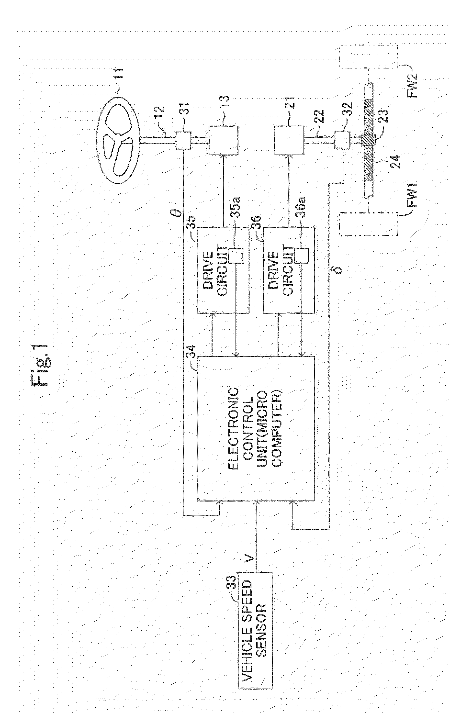
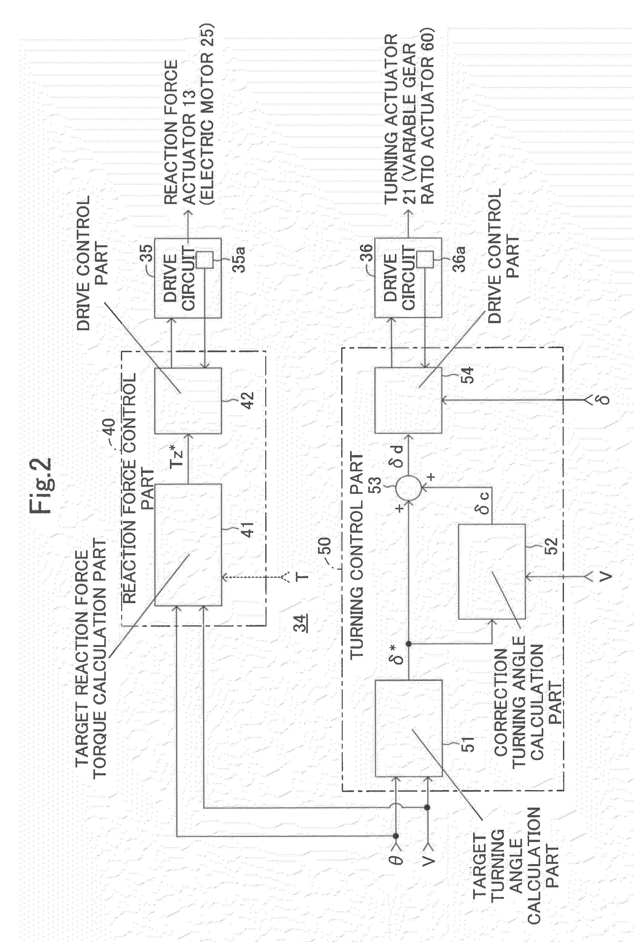
[0044]Below, steering devices of vehicles of the embodiments of the invention will be explained in detail by referring to the drawings. FIG. 1 schematically shows a steering device of a vehicle common to the first and second embodiments of the invention.

[0045]The steering device of the vehicle has a steering wheel 11 as an operation part which is rotated by the driver to turn right and left front wheels FW1 and FW2 which are wheels to be turned. The steering wheel 11 is secured to an upper end of a steering force input shaft 12, and a lower end of the steering force input shaft 12 is connected to a reaction force actuator 13 constituted by an electric motor and a reducer mechanism. The reaction force actuator 13 applies a reaction force to the rotation operation of the steering wheel 11 by the driver.

[0046]Further, the steering device of the vehicle has a turning actuator 21 constituted by an electric motor and a reducer mechanism. The turning force generated by t...

second embodiment

b. Second Embodiment

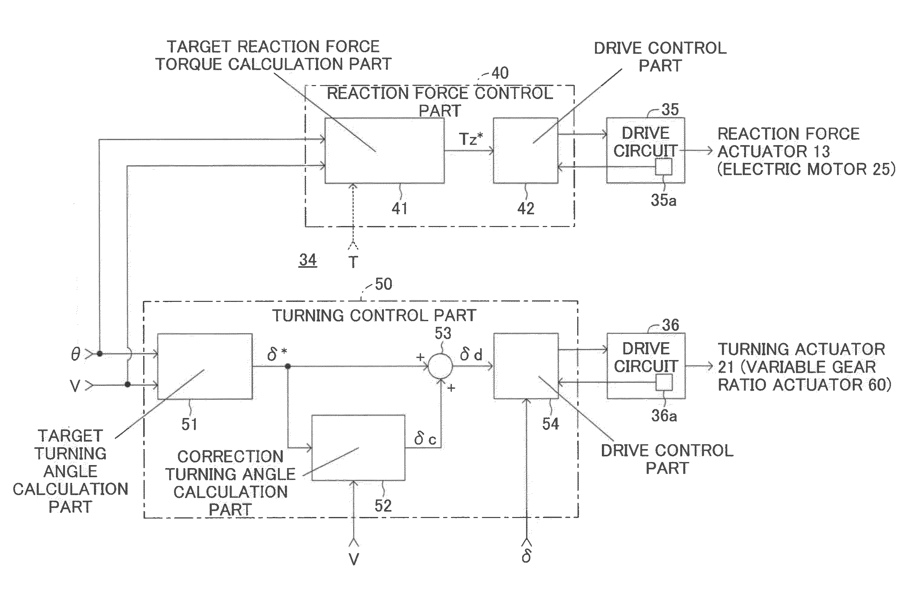
[0092]In the above-explained first embodiment, the correction turning angle calculation part 52 determines the transfer function K(s), which has as an input the target turning rate δ*′ and as an output the correction turning angle δc, by using the difference between the transfer function G(s) indicating the transient responsiveness property, which transfer function has as an input the turning angle δ and as an output the yaw rate γ, and the stationary component G(0) of the transfer function G(s). Further, the correction turning angle δc, which depends on the target turning rate δ*′, is calculated by using the transfer function K(s). Thereby, the change of the frequency responsiveness property of the yaw rate γ can be restricted, the directional stability of the vehicle at the high vehicle speed range can be ensured and the lag of the responsiveness at the low vehicle speed range can be improved.

[0093]In this regard, in the common vehicle, as shown in FIG. 10A, a ...

third embodiment

c. Third Embodiment

[0119]In the above-explained first and second embodiments, the steering-by-wire system, which the mechanical connection between the steering wheel 11 and the right and left front wheels FW1 and FW2 is released, is employed as the steering device of the vehicle. In this case, as shown in FIG. 15, the variable gear ratio steering device, which the steering gear ratio (the transmission ratio) can freely be adjusted, may be employed. Below, the third embodiment will be explained in detail, however, the same parts as those of the first and second embodiments are indicated by the same reference symbols as those of the first and second embodiments and the explanations thereof will be omitted.

[0120]In the steering device of the vehicle of the third embodiment, the reaction force actuator 13 and the turning actuator 21 of the first and second embodiments are omitted, and the steering force input shaft 12 and the turning force output shaft 22 are connected to each other by ...


PUM


Abstract

A target turning angle calculation part 51 calculates a target turning angle δ on the basis of a steering angle θ and a vehicle speed V. A correction turning angle calculation part 52 calculates a transfer function K(s) which is a second transfer function, depending on the vehicle speed V, by using a difference between a transfer function G(s) which is a first transfer function determined on the basis of the specification of the vehicle and a stationary component G(0) of the transfer function G(s), the first transfer function having as an input a turning angle δ and as an output a yaw rate γ of the vehicle, the second transfer function having as an input a target turning rate δ*′ obtained by temporally differentiating the target turning angle δ* and as an output a correction turning angle δc. The correction turning angle calculation part 52 calculates a correction turning angle δc by multiplying the transfer function K(s) by the target turning rate δ*′. A final target turning angle calculation part 53 inputs thereto the target turning angle δ* from the target turning angle calculation part 51 and the correction turning angle δc from the correction turning angle calculation part 52 and calculates a final target turning angle δd by adding the correction turning angle δc to the target turning angle δ*.

Description

TECHNICAL FIELD[0001]The present invention relates to a steering device of a vehicle, in particular, a steering device of a vehicle for turning wheels to be turned to a target turning amount, depending on an operation of a steering wheel by a driver.BACKGROUND ART[0002]Conventionally, a number of devices for improving a directional stability and responsiveness on the turning of the vehicle are proposed. For example, in the Japanese Unexamined Patent Publication No. 4-193684, a four-wheel steering device of a vehicle, which accomplishes an ideal transient responsiveness property on the steering of the front wheels, is disclosed. The prior four-wheel steering device of the vehicle comprises front-wheel turning angle control means for controlling the turning angles of the front wheels, depending on the running condition of the vehicle and rear-wheel turning angle control means for controlling the turning angles of the rear wheels, depending on the running condition of the vehicle. Furt...

Claims


Application Information

Patent Timeline
Patent Type & Authority Patents(United States)
IPC IPC(8): G06F19/00
CPCB62D6/001B62D6/002B62D6/02
Inventor YAMAZAKI, IPPEI
Owner TOYOTA JIDOSHA KK
Why Eureka
Try Eureka