Failure recovery method in cluster system

a cluster system and failure recovery technology, applied in the field of cluster system failure recovery technology, can solve the problems of inability to perform recovery processing, inability to execute recovery processing, and longer processing time compared with system switching to standby system, so as to increase the speed and reliability of processing.

Inactive Publication Date: 2011-02-08
HITACHI LTD
View PDF8 Cites 0 Cited by
  • Summary
  • Abstract
  • Description
  • Claims
  • Application Information

AI Technical Summary

Benefits of technology

[0007]An object of this invention is to provide a process recovery method with which the speed of the recovery processing is increased while the possibility of loss of processing data is minimized.
[0009]According to an aspect of this invention, the speed and reliability of the processing can be increased by determining which of the process restart and the system switching is performed, based on the system state.

Problems solved by technology

In a cluster system using a volatile memory instead of a nonvolatile shared disk to improve the processing performance, when a process failure has occurred in the active system, the recovery processing cannot be performed because data is lost.
However, according to the technology disclosed in JP 09-168015 A, because the data is merely duplicately protected, the recovery processing cannot be executed, if a failure has occurred in the computer where the data is copied, before the completion of the process restart.
Moreover, because the process restart by the same system is invariably executed and data transfer from another system is attempted when a process failure has occurred in the active system, there is a possibility that the processing time may become longer compared with system switching to the standby system.

Method used


Image

  • Failure recovery method in cluster system
  • Failure recovery method in cluster system
  • Failure recovery method in cluster system

Examples


first embodiment

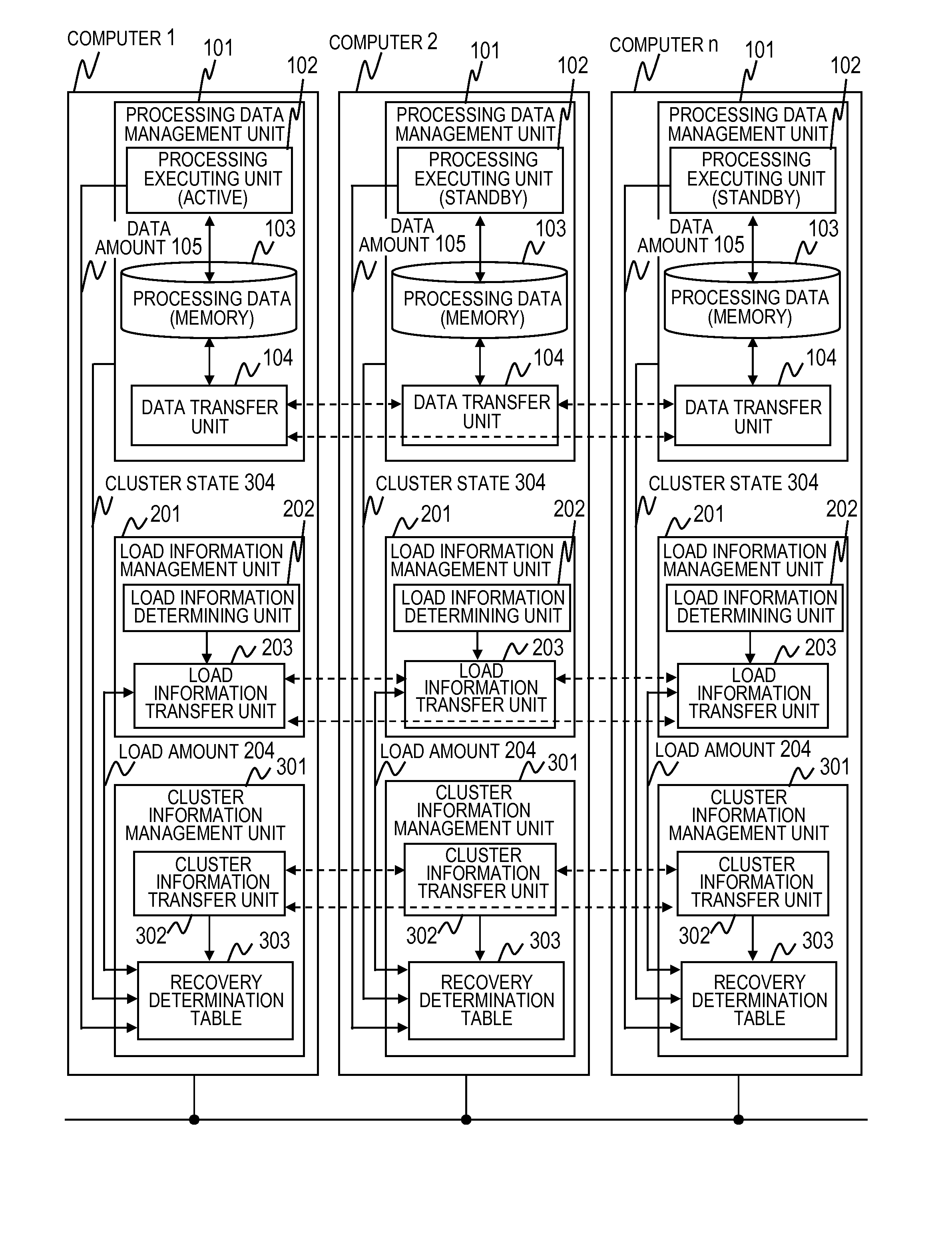
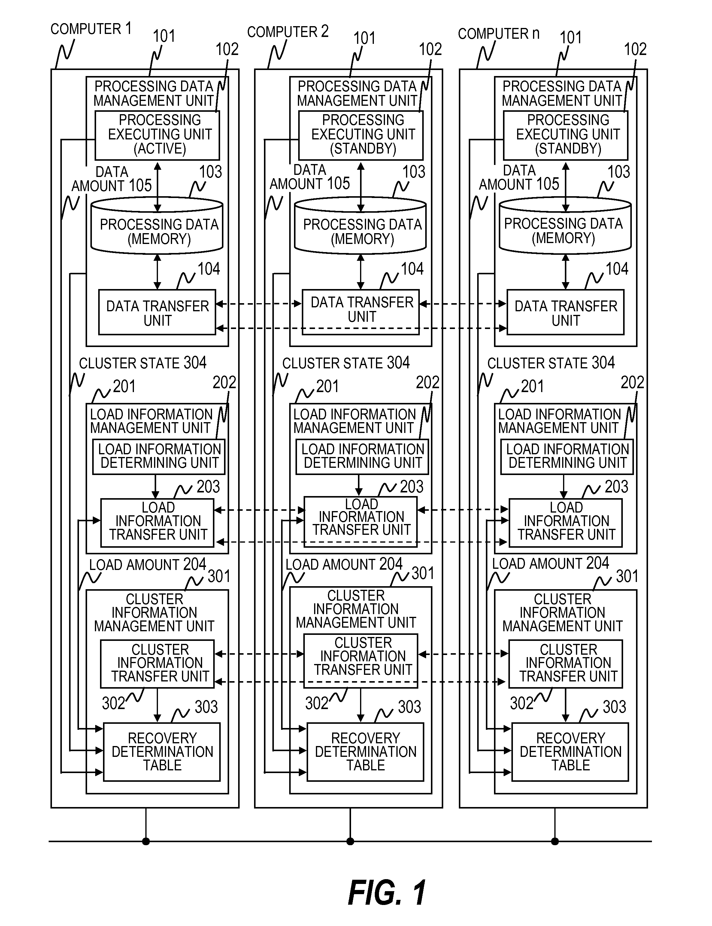
[0025]FIG. 1 is a system structure diagram showing an example of a cluster system of a first embodiment of this invention.

[0026]The cluster system of the first embodiment of this invention includes an active system computer 1 and a plurality of standby system computers 2 to n.

[0027]The active system computer and the standby system computer each include a processing data management unit 101, a load information management unit 201, and a cluster information management unit 301. The active system computer and the standby system computer included in the cluster system have the same structure. When the processing of the active system computer is taken over by a standby system computer by system switching, the standby system computer taking over the processing operates as the active system computer thereafter. If possible, the computer that operated as the active system computer may be operated as a standby system computer.

[0028]The processing data management unit 101 has a processing exe...

second embodiment

[0095]While the recovery determination table 303 is held by each computer in the first embodiment of this invention, the recovery determination table 303 is held by a management computer in the second embodiment of this invention. Further, the management computer determines the process failure recovery method, and instructs the computers to use the method.

[0096]FIG. 11 is a system block diagram showing an example of a cluster system of a second embodiment of this invention.

[0097]The cluster system of the second embodiment of this invention includes a management computer 11 in addition to the active system computer and the standby system computer (1 to n). The active system computer and the standby system computer (1 to n) and the management computer 11 are coupled through a network.

[0098]The management computer 11 holds the cluster state determination table 331 and the load information determination table 321, and determines whether to restart the process or switch to a standby syst...


PUM


Abstract

There is provided a method executed in a cluster system comprising a first computer and at least one second computer that stores the data transmitted from the first computer. The method comprising the steps of: judging whether the failure-occurred processing is restarted by the first computer or the failure-occurred processing is switched over by the second computer based on the system information; receiving the stored data from the second computer and re-executing the processing in which the failure has occurred by the first computer, in the case of which it is judged that the processing in which the failure has occurred is restarted by the first computer; and executing, by the second computer, the processing in which the failure has occurred, in the case of which it is judged that the processing in which the failure has occurred is switched over by the at least one second computer.

Description

CLAIM OF PRIORITY[0001]The present application claims priority from Japanese patent applications JP 2007-307106 filed on Nov. 28, 2007, the content of which are hereby incorporated by reference into this application.BACKGROUND OF THE INVENTION[0002]This invention relates to a technology of recovering a failure in a cluster system including an active system computer and a standby system computer.[0003]Conventionally, in a cluster system in which processing data is held in a nonvolatile shared disk and which includes an active system computer and a standby computer, when a failure has occurred in the process of the active system, recovery from the failure is performed by restarting the process or switching to a standby system.[0004]In a cluster system using a volatile memory instead of a nonvolatile shared disk to improve the processing performance, when a process failure has occurred in the active system, the recovery processing cannot be performed because data is lost. Therefore, as...

Claims


Application Information

Patent Timeline
Patent Type & Authority Patents(United States)
IPC IPC(8): G06F11/00
CPCG06F11/0709G06F11/2025G06F11/2043G06F11/0793G06F11/1438G06F11/2041
Inventor MATSUMOTO, HIROKAZUBABA, TSUNEHIKOHAMADA, SHINJIICHIMURA, TAKASHITAKAHASHI, NORIAKI
Owner HITACHI LTD
Why Eureka
Try Eureka