

Machine tool
a technology of machine tools and tools, applied in the field of machine tools, can solve the problems of high cost of machine tools and manufacturing costs
- Summary
- Abstract
- Description
- Claims
- Application Information
AI Technical Summary
Benefits of technology
Problems solved by technology
Method used
Image

Examples
Embodiment Construction
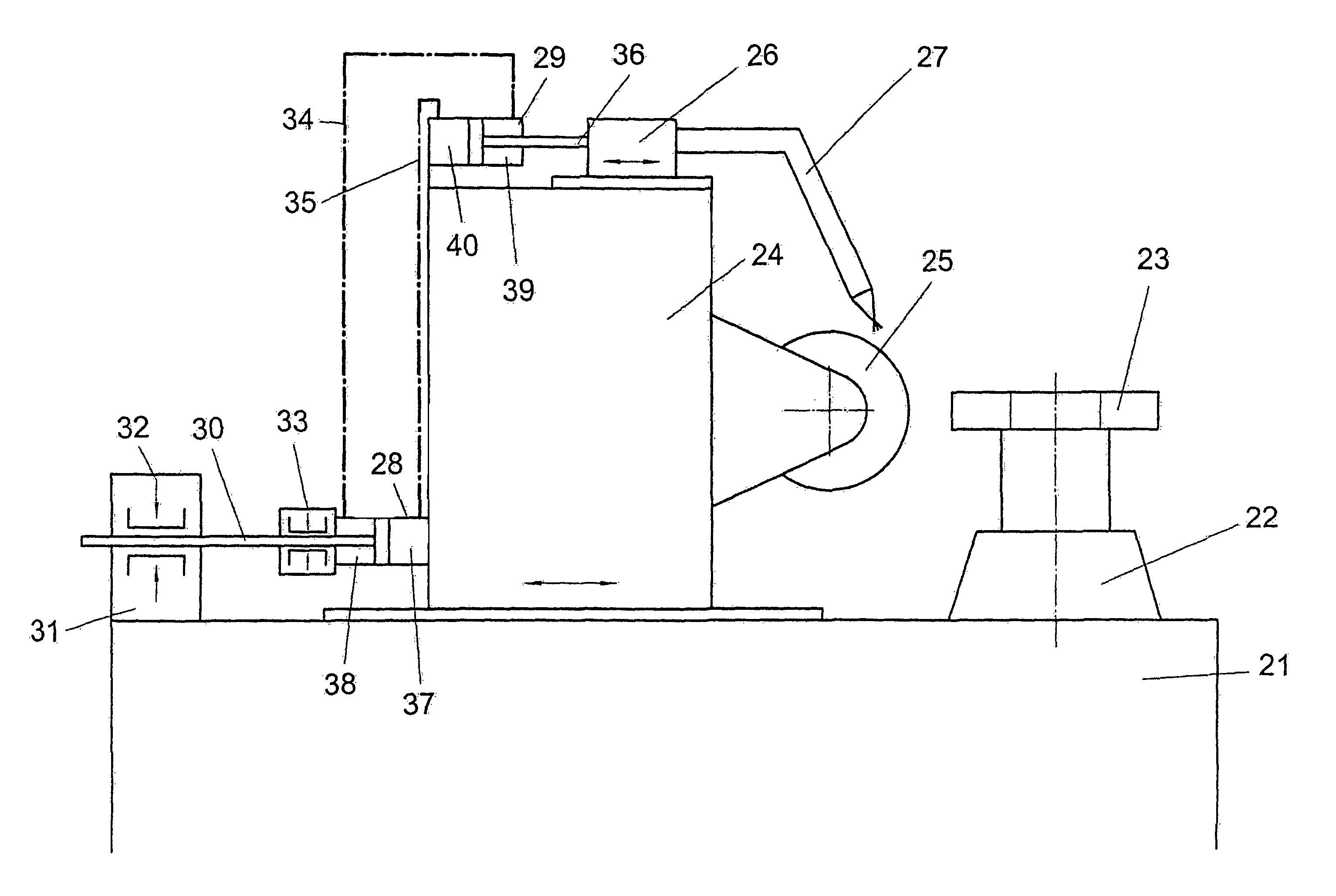
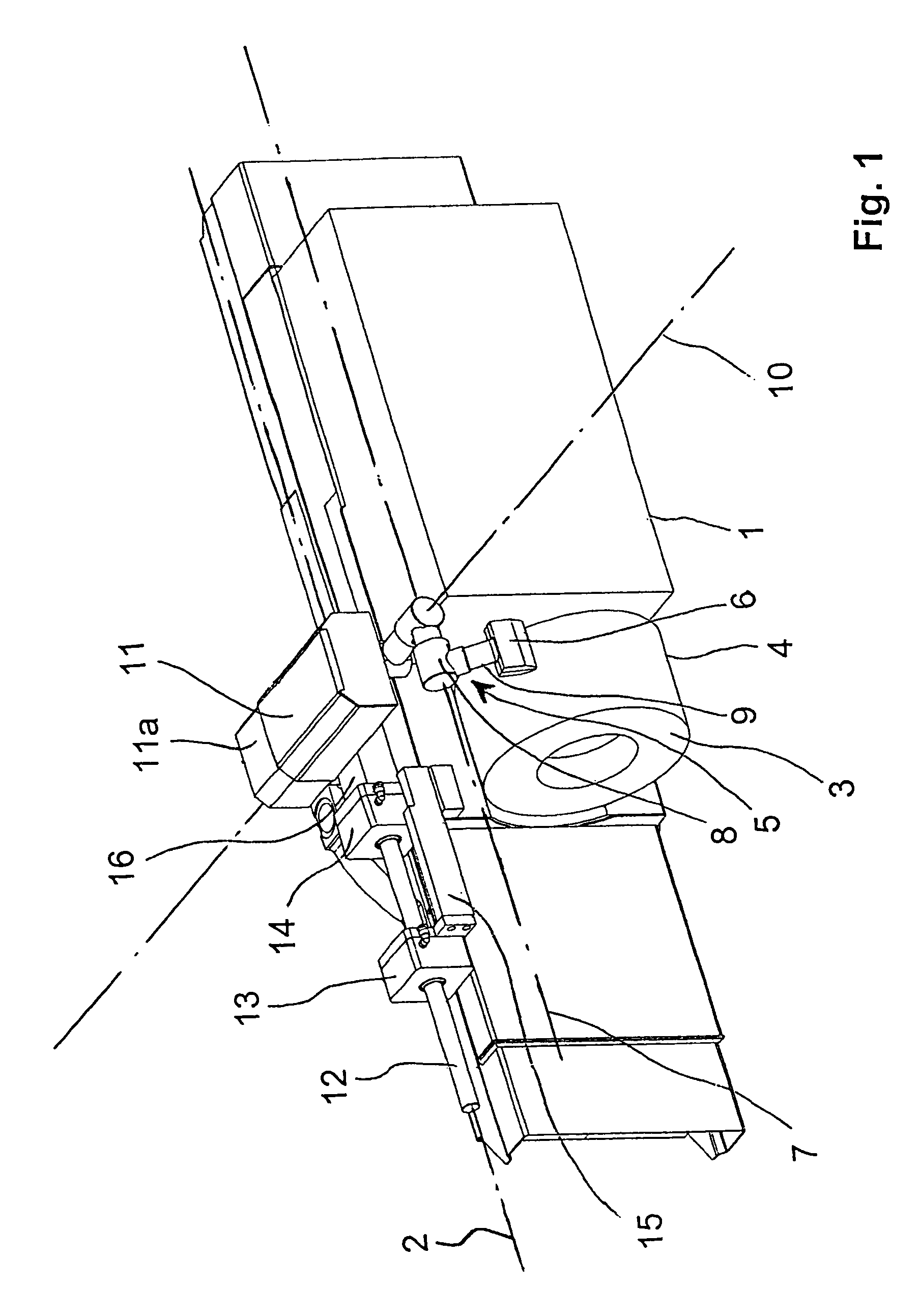
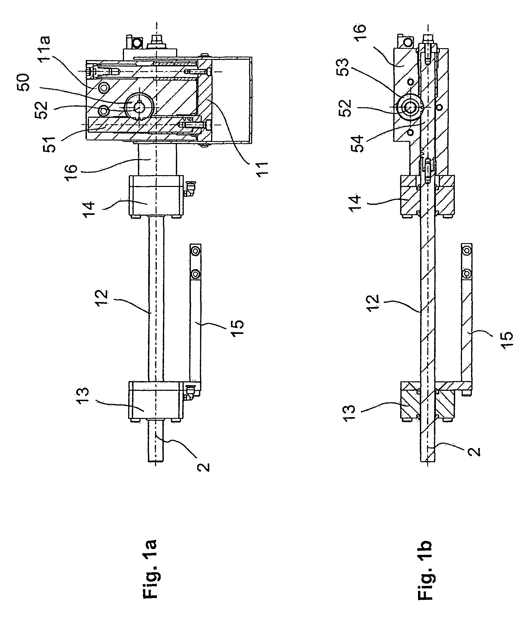
[0011]The invention begins with the observation that axes of movement, unless they represent completely independent degrees of freedom, do not necessarily have to be served by individual drive mechanisms with dedicated drive motors. Rather, according to the invention, a dedicated drive motor for the second function-supporting unit is dispensed with, and the power to move the second function-supporting unit is derived from the movement of the first function-supporting unit which is driven by its controlled drive motor. Under this concept, when the first coupler unit is in its engaged state, the second displacement-actuator unit at its drive-output section translates the movement introduced at its drive-input section from the first function-supporting unit into a movement of the second function-supporting unit. On the other hand, when the first coupler unit is switched to its disengaged condition, the second function-supporting unit remains in the position corresponding to the second ...
PUM
| Property | Measurement | Unit |
|---|---|---|
| displacement | aaaaa | aaaaa |
| pressure | aaaaa | aaaaa |
| hydraulic pressure | aaaaa | aaaaa |
Abstract
Description
Claims
Application Information