Conveyor belt

a conveyor belt and belt technology, applied in the direction of belt/chain/gearing, driving chain, chain element, etc., can solve the problems of conveyor belt breakdown, conveyor belt area reduction, and inability to use as smooth as desired, so as to achieve strong linkage, reduce the effect of belt breakdown, and high reliability in operation

Active Publication Date: 2009-01-29
JOHN BEAN TECH AB
View PDF9 Cites 1 Cited by
  • Summary
  • Abstract
  • Description
  • Claims
  • Application Information

AI Technical Summary

Benefits of technology

[0010]It is also an object of the invention to provide such a conveyor belt which also in case of high level stress exposure has a high reliability in operation.
[0013]Hereby an improved conveyor belt is achieved. Since the rod receiving holes of each plate have an offset in the direction towards the first side of the plate, it will be possible to ensure that the links do not project from the load-carrying surface of the conveyor belt by arranging the links such that the first side of each plate faces said load-carrying surface. The offset will result in the formation of a thin portion with a thickness of material between the holes and the first side of the plate. However, the provision of the recess in said first side of the plate results in a direction of a major part of tractive forces applied to the plate towards a thick portion with a thickness of material formed between the holes and a second side of the plate, thereby making it possible to make the link sufficiently strong. Consequently, the unique configuration of the link makes it possible to obtain a conveyor belt with a smooth load-carrying surface, which conveyor belt at the same time exhibit a high reliability in operation even in case of high level stress exposure.
[0014]According to an embodiment of the invention conveyor belt, the transverse rods may support a wire mesh for forming a load-carrying surface of the conveyor belt, said wire mesh being formed by a plurality of wires. In this case, the rod receiving holes of each plate may have such an offset towards said first side of the plate that a thickness of material between each hole and said first side essentially corresponds to a wire diameter of said wires. Hereby it will be possible to obtain a smooth load-carrying surface of the belt.
[0015]According to another embodiment, the recess of each plate may have a rounded curvature. The rounded curvature of the recess makes it possible to level out stresses applied to each link when subjected to tractive forces and especially stresses applied to the thin portion formed between the rod receiving holes and the first side of the plate. The curvature may be such that a section, including said thin portion, with an uniform thickness of material is formed.
[0017]According to yet another embodiment, the rod receiving holes of each plate may be elongate holes having an extension parallel with a longitudinal axis of the plate. This will result in a further levelling out of stresses applied to the link.

Problems solved by technology

However, this requires a substantial collapsing of the corresponding inner side of the belt when transferring from a straight path to a helical path, thereby reducing the area of the belt in its straight stat that can be used in the curved state of the conveyor belt, unless the outer side is expanded at the same time as the inner side is collapsed.
Also, the links project above the load-carrying surface of the belt such that it is not as smooth as desired.
However, in certain cases the joint may break due to high level stress exposure resulting in a conveyor belt breakdown.

Method used


Image

  • Conveyor belt
  • Conveyor belt
  • Conveyor belt

Examples


Embodiment Construction

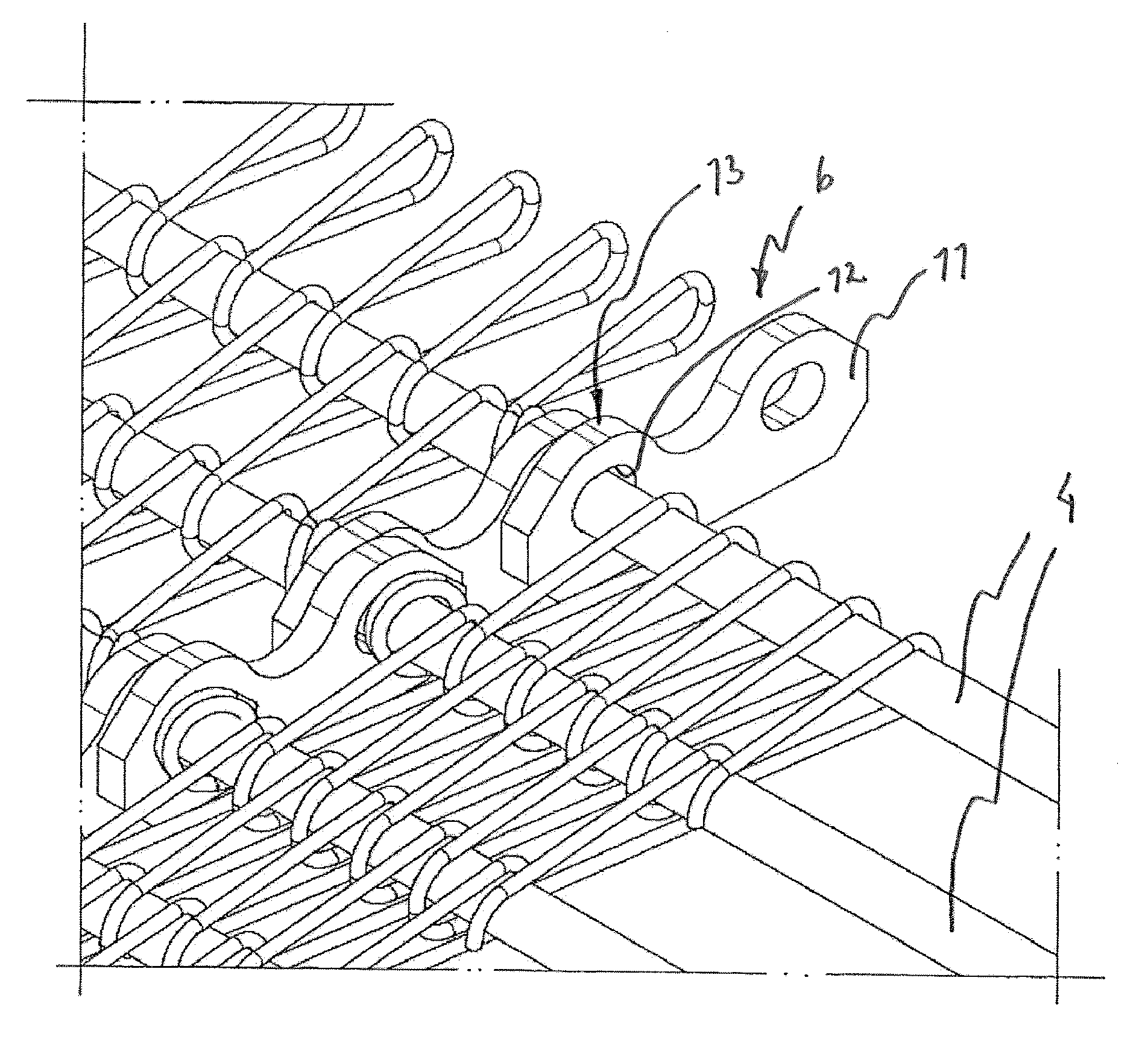
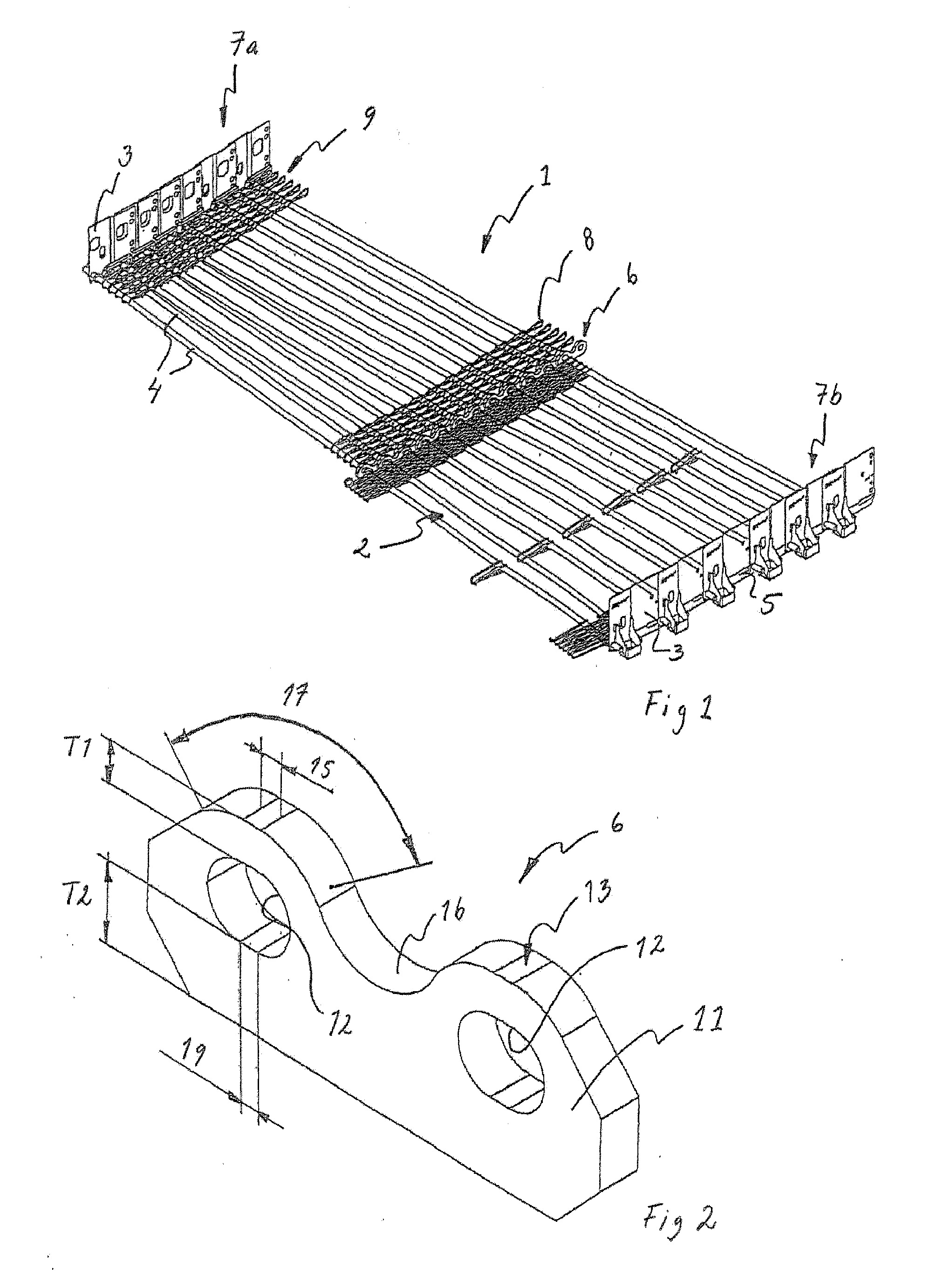
[0026]In FIG. 1, to which reference now is made, illustrates a section of a conveyor belt 1 in accordance with the invention.

[0027]The conveyor belt 1 may be used for an air conditioning plant, in which the conveyor belt 1 is endless and extends helically along part of its length. The conveyor belt 1 can be intended for conveying of foodstuffs, which will be chilled, frozen or cooked when conveyed through the air conditioning plant.

[0028]However, it will be appreciated that the inventive conveyor belt 1 can also be used for other applications than air conditioning plants.

[0029]The conveyor belt 1 comprises a plurality of successive belt elements 2, which each have two lateral side members 3 and two rods 4 extended between and fixedly connected to the side members 3. This structure results in a relatively rigid frame structure, giving the conveyor belt a good load-bearing capacity.

[0030]The conveyor belt 1 may be supported or of a wholly, or partly, self-supporting type.

[0031]By a se...


PUM


Abstract

A conveyor belt comprising a plurality of successive belt elements (2), each belt element (2) comprising at least one transverse rod (4) and two opposing side members (3) connected to each other by the at least one transverse rod (4), and a link (6) forming a joint intermediate the lateral edges (7a, 7b) of the conveyor belt between the adjoining transverse rods (4) of each pair of adjoining belt elements (2). Each link (6) comprises a plate (11) in which two successive rod receiving holes (12) are formed, wherein the rod receiving holes (12) have an offset (O) towards a first side (13) of said plate (11) and wherein a recess (16) is formed in said first side (13) of the plate (11), between said rod receiving holes (12).

Description

FIELD OF THE INVENTION[0001]The present invention relates to a conveyor belt and more specifically to a conveyor belt comprising a plurality of successive belt elements, each belt element comprising at least one transverse rod and two opposing side members connected to each other by the at least one transverse rod, wherein a joint is arranged intermediate the lateral edges of the conveyor belt between the adjoining transverse rods of each pair of adjoining belt elements.BACKGROUND ART[0002]The above type of conveyor belt is advantageous for inter alia air treatment of food products in cooling, freezing or cooking the food products. The conveyor belt is often made to follow a helical path forming a stack of helically wound tiers.[0003]Each belt element is movable relative to adjoining belt elements about two axes perpendicular to the longitudinal direction of the belt and situated one in the plane of the belt and the other perpendicular thereto.[0004]In order to make as full use as p...

Claims


Application Information

Patent Timeline
Patent Type & Authority Applications(United States)
IPC IPC(8): F16G13/06
CPCB65G17/064
Inventor GRAMBY, GORANWILTHORN, URBAN
Owner JOHN BEAN TECH AB
Why Eureka
Try Eureka