Gate valve apparatus for vacuum processing system

a vacuum processing system and valve body technology, applied in the direction of valve details, valve arrangement, operating means/releasing devices, etc., can solve the problems of high equipment cost and large installation space, complicated structure of elevating mechanism for moving the valve body up and down, and requiring a large installation space, etc., to achieve the effect of reducing cost, simple structure and reducing equipment cos

Inactive Publication Date: 2007-10-16
TOKYO ELECTRON LTD
View PDF21 Cites 2 Cited by
  • Summary
  • Abstract
  • Description
  • Claims
  • Application Information

AI Technical Summary

Benefits of technology

[0009]An object of the present invention is to provide a gate valve apparatus for a vacuum processing system, which has a simple structure to realize a smaller size and a lower cost, while maintaining high reliability in operation.

Problems solved by technology

In conventional gate valve apparatuses, the structures of an elevating mechanism for moving a valve body up and down and a pushing mechanism for pushing the valve body against a transfer port are complicated and bulky.
Consequently, they require a high equipment cost and a large installation space, and entail problems in reliability due to the complexity of the structure.

Method used


Image

  • Gate valve apparatus for vacuum processing system
  • Gate valve apparatus for vacuum processing system
  • Gate valve apparatus for vacuum processing system

Examples


Embodiment Construction

[0048]An embodiment of the present invention will now be described with reference to the accompanying drawings. In the following description, the constituent elements having substantially the same function and arrangement are denoted by the same reference numerals, and a repetitive description will be made only when necessary.

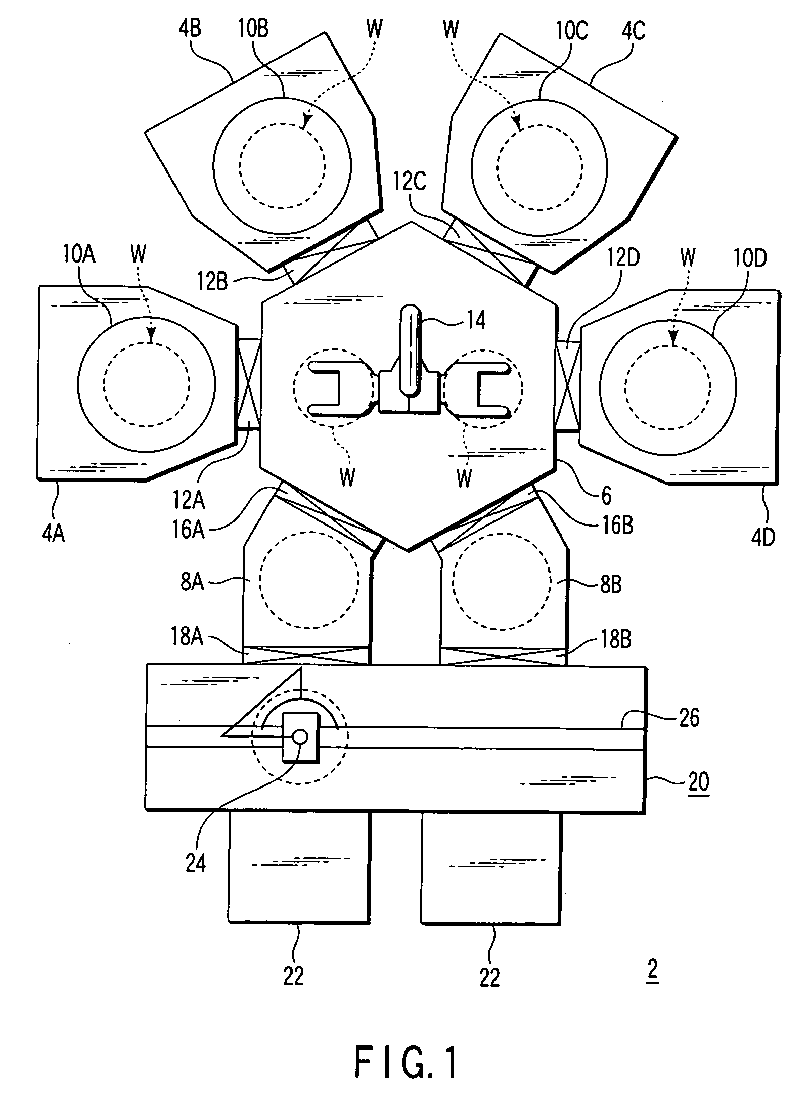
[0049]FIG. 1 is a plan view showing a processing system using gate valve apparatuses according to an embodiment of the present invention. As shown in FIG. 1, the processing system 2 includes a hexagonal common transfer chamber 6. Four process chambers 4A, 4B, 4C and 4D and two load-lock chambers 8A and 8B are connected to the common transfer chamber 6.

[0050]Specifically, each of the process chambers 4A to 4D is constructed such that the inner pressure thereof is adjustable by gas supply and vacuum-exhaust. The process chambers 4A to 4D include worktables 10A, 10B, 10C, and 10D, respectively, for placing a target object or semiconductor wafer W thereon. While th...


PUM


Abstract

A gate valve apparatus includes a valve body to open and close a target object transfer port in a vacuum processing system. The valve body is reciprocated in a first direction relative to the transfer port. A support rod is connected to the valve body and extends in the first direction. A driving mechanism is configured to drive the valve body through the support rod. The driving mechanism includes a movable shaft structure reciprocated in a second direction perpendicular to the first direction. A first cam structure coupling the movable shaft structure to the support rod includes a portion that converts reciprocation movement of the movable shaft structure in the second direction into reciprocation movement of the support rod in the first direction. A swing drive is configured to swing the support rod and valve body about the central axis of the movable shaft structure.

Description

CROSS-REFERENCE TO RELATED APPLICATIONS[0001]This application claims the benefit of U.S. Provisional Application No. 60 / 675,889, filed Apr. 29, 2005.[0002]This application is based upon and claims the benefit of priority from prior Japanese Patent Application No. 2005-115111, filed Apr. 12, 2005, the entire contents of which are incorporated herein by reference.BACKGROUND OF THE INVENTION[0003]1. Field of the Invention[0004]The present invention relates to a gate valve apparatus for a vacuum processing system and a semiconductor processing system including a plurality of process chambers. The term “semiconductor process” used herein includes various kinds of processes which are performed to manufacture a semiconductor device or a structure having wiring layers, electrodes, and the like to be connected to a semiconductor device, on a target object, such as a semiconductor wafer or a glass substrate used for an LCD (Liquid Crystal Display) or FPD (Flat Panel Display), by forming semic...

Claims


Application Information

Patent Timeline
Patent Type & Authority Patents(United States)
IPC IPC(8): F16K31/00
CPCF16K51/02F16K1/24
Inventor HIROKI, TSUTOMU
Owner TOKYO ELECTRON LTD
Why Eureka
Try Eureka