
System and method for aligning RGB light in a single modulator projector

a technology of modulator and light, applied in the field of visual display devices, can solve the problems of insufficient operation speed, and inability to operate fast for lcos and lcd chips

Inactive Publication Date: 2011-02-22
EVANS & SUTHERLAND COMP
View PDF888 Cites 22 Cited by
  • Summary
  • Abstract
  • Description
  • Claims
  • Application Information

AI Technical Summary

Benefits of technology

[0021]The features and advantages of the disclosure will be set forth in the description which follows, and in part will be apparent from the description, or may be learned by the practice of the disclosure without undue experimentation. The features and advantages of the disclosure may be realized and obtained by means of the instruments and combinations particularly pointed out in the appended claims.

Problems solved by technology

Disadvantageously, DMD based projectors are susceptible to a “screen door” effect which is commonly described as viewing an image through a screen door.
The undesirable effect is due to the fact that the individual micro-mirrors have gaps between them.
Because they cannot operate fast enough when operating in a sequential fashion, both LCOS and LCD projectors deliver the red, green and blue components of light to the screen simultaneously.
Since LCOS and LCD chips cannot operate fast enough, there is no spinning color wheel used in these projectors as there is in single-chip DMD based projectors.
This DMD technology is susceptible to color separation, also known as the rainbow effect, where light or white images that are in motion on a dark background appear to have a rainbow or shadow of colors following the image.
DMD based systems have made improvements to its color rendition by sometimes adding an additional set of red, green and blue filters to its color wheel and improving the rotational speed of the wheel to help reduce the visible effects of color separation to some of the population viewing the image, however, it does not eliminate the problem altogether.
In addition to color separation problems, some technologies, and particularly technologies based upon LCDs, display an undesirable characteristic called color divergence and is due to misalignment of the three modulators.
However, the use of three light modulating devices increases the cost, weight, power requirements and complexity of the projection system.

Method used


Image

  • System and method for aligning RGB light in a single modulator projector
  • System and method for aligning RGB light in a single modulator projector
  • System and method for aligning RGB light in a single modulator projector

Examples


Embodiment Construction

[0033]For the purposes of promoting an understanding of the principles in accordance with the disclosure, reference will now be made to the embodiments illustrated in the drawings and specific language will be used to describe the same. It will nevertheless be understood that no limitation of the scope of the disclosure is thereby intended. Any alterations and further modifications of the inventive features illustrated herein, and any additional applications of the principles of the disclosure as illustrated herein, which would normally occur to one skilled in the relevant art and having possession of this disclosure, are to be considered within the scope of the disclosure claimed.

[0034]The publications and other reference materials referred to herein to describe the background of the disclosure, and to provide additional detail regarding its practice, are hereby incorporated by reference herein in their entireties, with the following exception: In the event that any portion of said...


PUM


Abstract

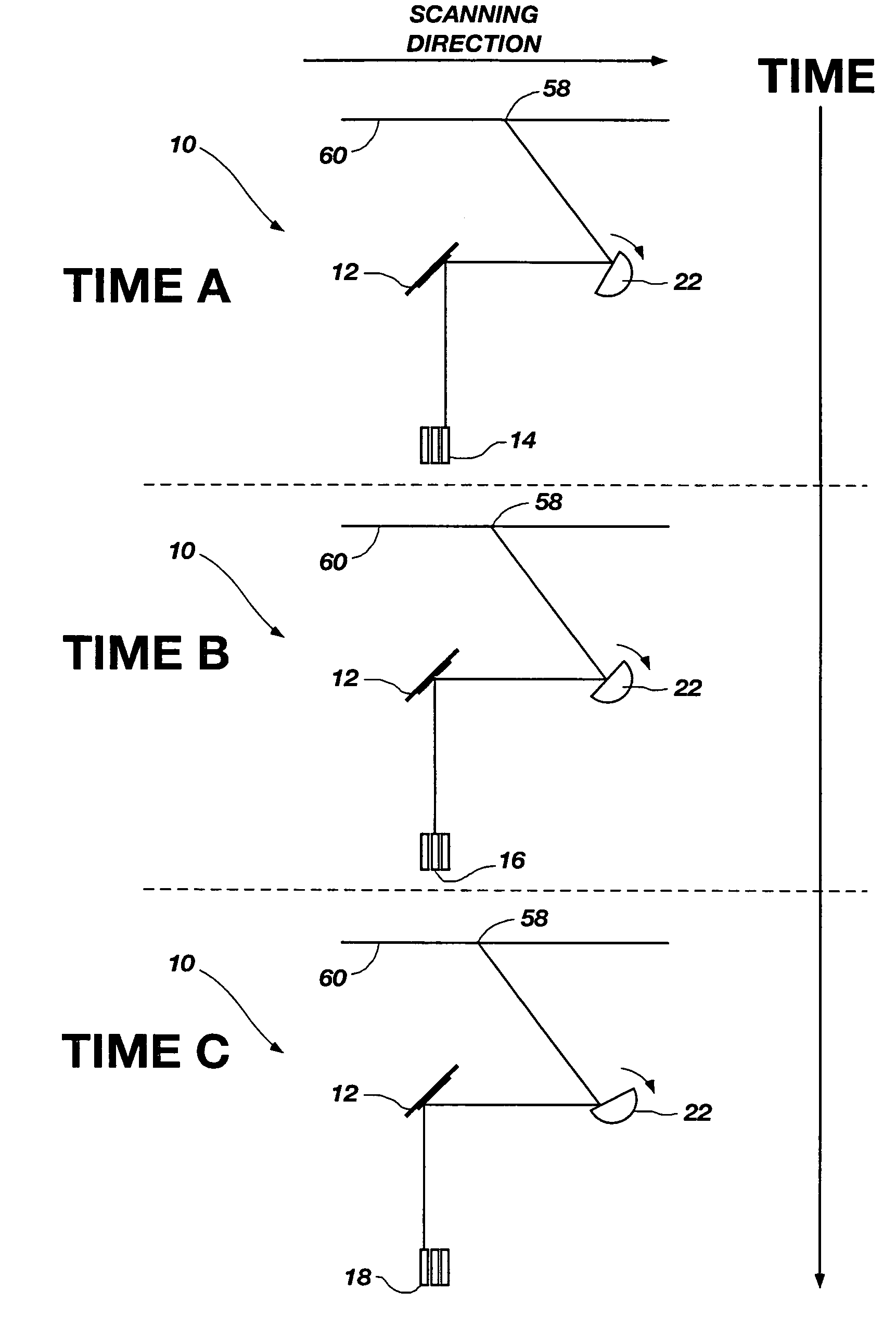
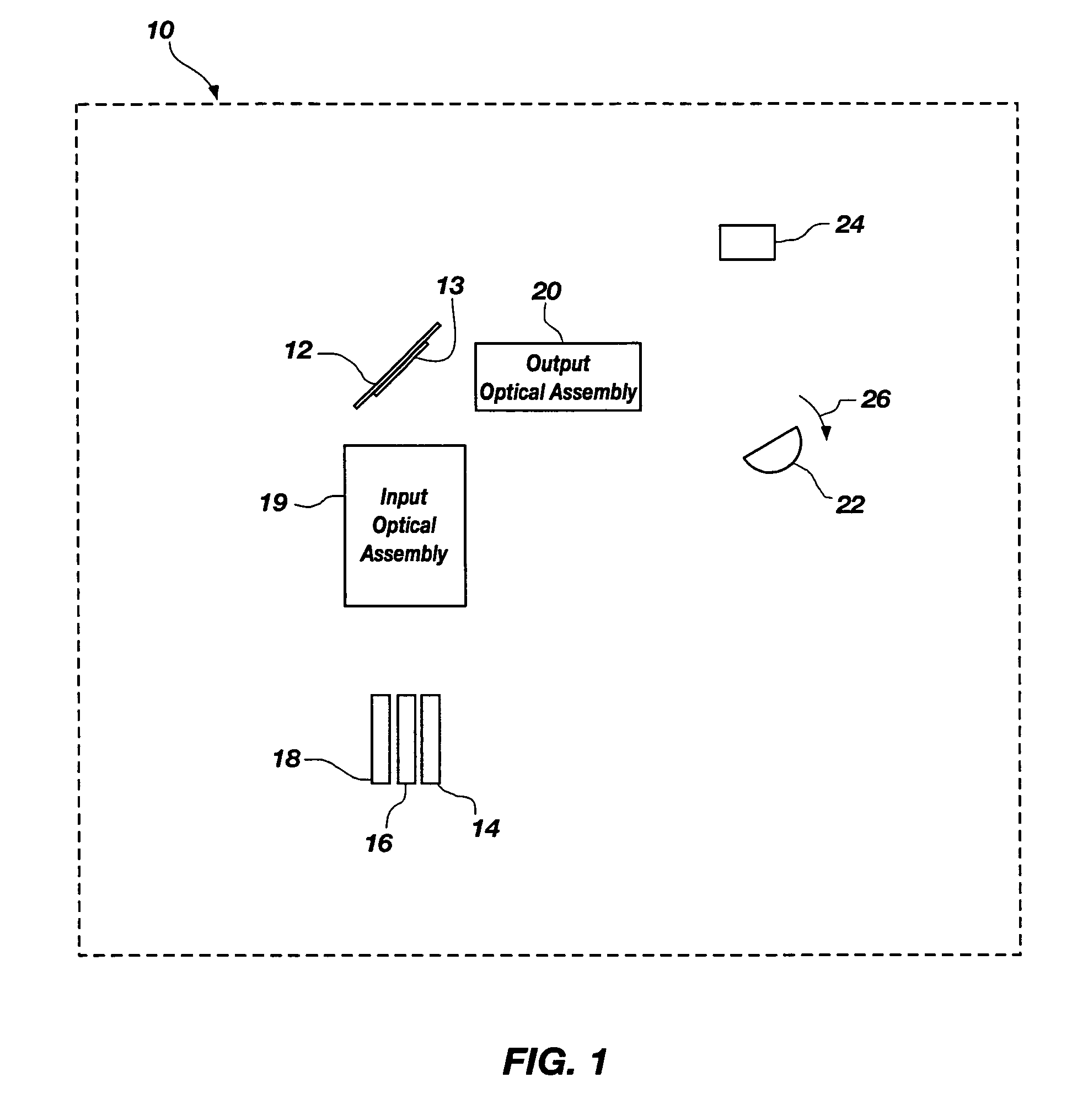
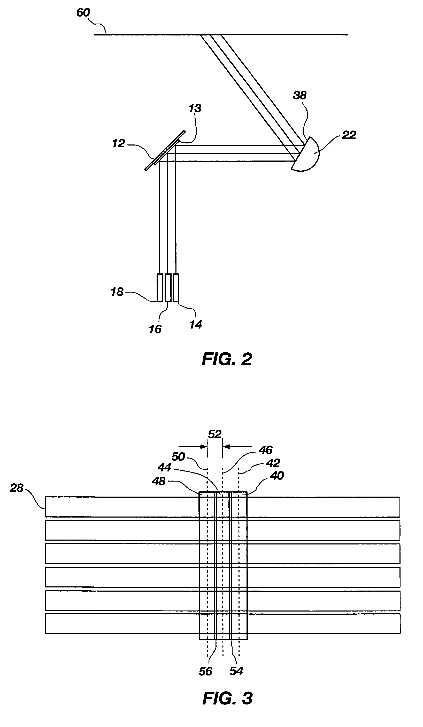
A projection system that includes a singe light modulation device and a plurality of light sources of different wavelengths. Each wavelength of light is incident on the light modulation device at a spatially distinct location and a temporally distinct time. The use of a scanning mirror allows the projection system to sequentially form, in full-color, each of the columns or rows of an image. The projection system is characterized by the reduction of color separation or the rainbow effect due to the rendering of each column or row in full color.

Description

CROSS-REFERENCE TO RELATED APPLICATIONS[0001]This application claims the benefit of U.S. Provisional Application No. 60 / 874,605, filed Dec. 12, 2006 which is hereby incorporated by reference herein in its entirety, including but not limited to those portions that specifically appear hereinafter, the incorporation by reference being made with the following exception: In the event that any portion of the above-referenced provisional application is inconsistent with this application, this application supercedes said above-referenced provisional application.STATEMENT REGARDING FEDERALLY SPONSORED RESEARCH OR DEVELOPMENT[0002]Not Applicable.BACKGROUND[0003]1. The Field of the Invention[0004]The present invention relates generally to visual display devices, and more particularly, but not necessarily entirely, to visual display devices containing light modulating devices.[0005]2. Description of Background Art[0006]Dynamic video displays are becoming ubiquitous in modern society. Such video...

Claims


Application Information

Patent Timeline
Patent Type & Authority Patents(United States)
IPC IPC(8): G03B21/00
CPCG03B21/20G03B27/547G03B33/06G03B21/005H04N9/3111H04N9/3164G03B33/08
Inventor CHRISTENSEN, ROBERT R.WINKLER, BRET D.ELKINS, DENNISTANNER, ALLEN H.
Owner EVANS & SUTHERLAND COMP
Learn More