Multi-layer film and image display device

a multi-layer film and image display technology, applied in the field of multi-layer film and image display devices, can solve the problems of difficult to enhance the adhesive strength to a predetermined level, difficult to prevent light reflection, and light leakage, and achieve excellent adhesive strength, prevent rainbow unevenness, and excellent rub resistance

Inactive Publication Date: 2008-01-17
FUJIFILM CORP
View PDF1 Cites 15 Cited by
  • Summary
  • Abstract
  • Description
  • Claims
  • Application Information

AI Technical Summary

Benefits of technology

[0015]According to the present invention, it is possible to provide a multi-layer film having a multi-layer structure in which a first layer and a second layer are stacked on a base material formed of polyester in this order from a side of the base material. The multi-layer film has excellent adhesive strength between materials and prevents occurrence of rainbow unevenness. As a second layer, an optically functional layer such as a hard coat layer and an antireflection layer, and physically functional layer excellent in rub resistance are formed. Thereby, it is possible to obtain an optical film having excellent optical properties such as a hard coat film and an antireflection film. Additionally, by using the optical film thus obtained as its component, it is possible to obtain an image display device exhibiting excellent displaying quality.

Problems solved by technology

However, in a case where adhesive strength between the base material and the upper layer is low, the upper layer may be peeled from the base material, thus causing light leakage and making it impossible to prevent light from reflecting.
Therefore, the adhesive strength is important in the multi-layer film, however, it is difficult to enhance the adhesive strength to a predetermined level since the adhesive strength tends to be easily affected by material composition of the base material and the upper layer, irregularities on the contact surface, formation condition of each layer, and the like.
Further, when light is reflected on the interfaces, the reflected light interfere with each other to cause a phenomenon in which the light seems rainbow (rainbow unevenness).
Accordingly, displaying quality in using the multi-layer film drastically deteriorates.
In particular, in a case where thickness irregularity exists on the upper layer, the reflected light becomes more intense at a certain thickness, and rainbow unevenness is more apparent on the multi-layer film, thus causing a problem.
However, in this case, the fine particles, the chelate compound, or the like precipitates between the base material and the adhesion assist layer, and between the adhesion assist layer and the upper layer, and then the adhesive strength therebetween decreases, thus causing a problem.
Furthermore, when a large amount of fine particles are added for the purpose of increasing the refractive index, strength of each of the layers decreases, thus consequently causing deterioration of the film as a whole.
However, such a polymer is expensive mostly, and therefore manufacturing cost increases, thus causing a problem.

Method used


Image

  • Multi-layer film and image display device
  • Multi-layer film and image display device

Examples


example 1

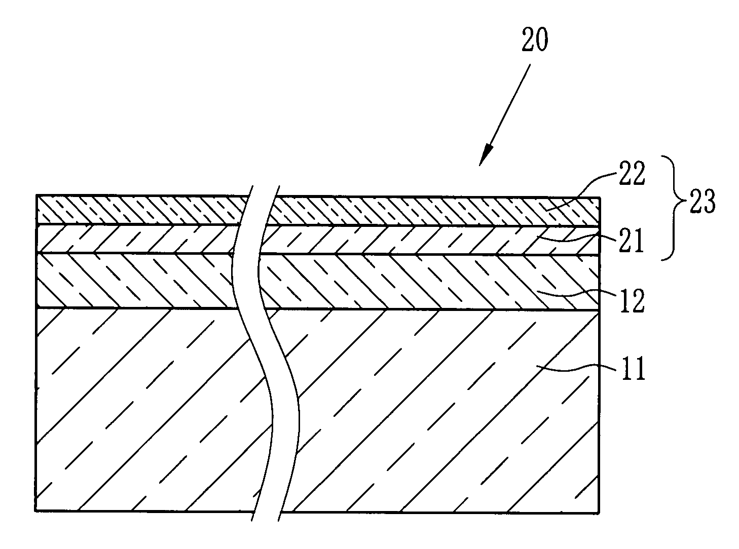
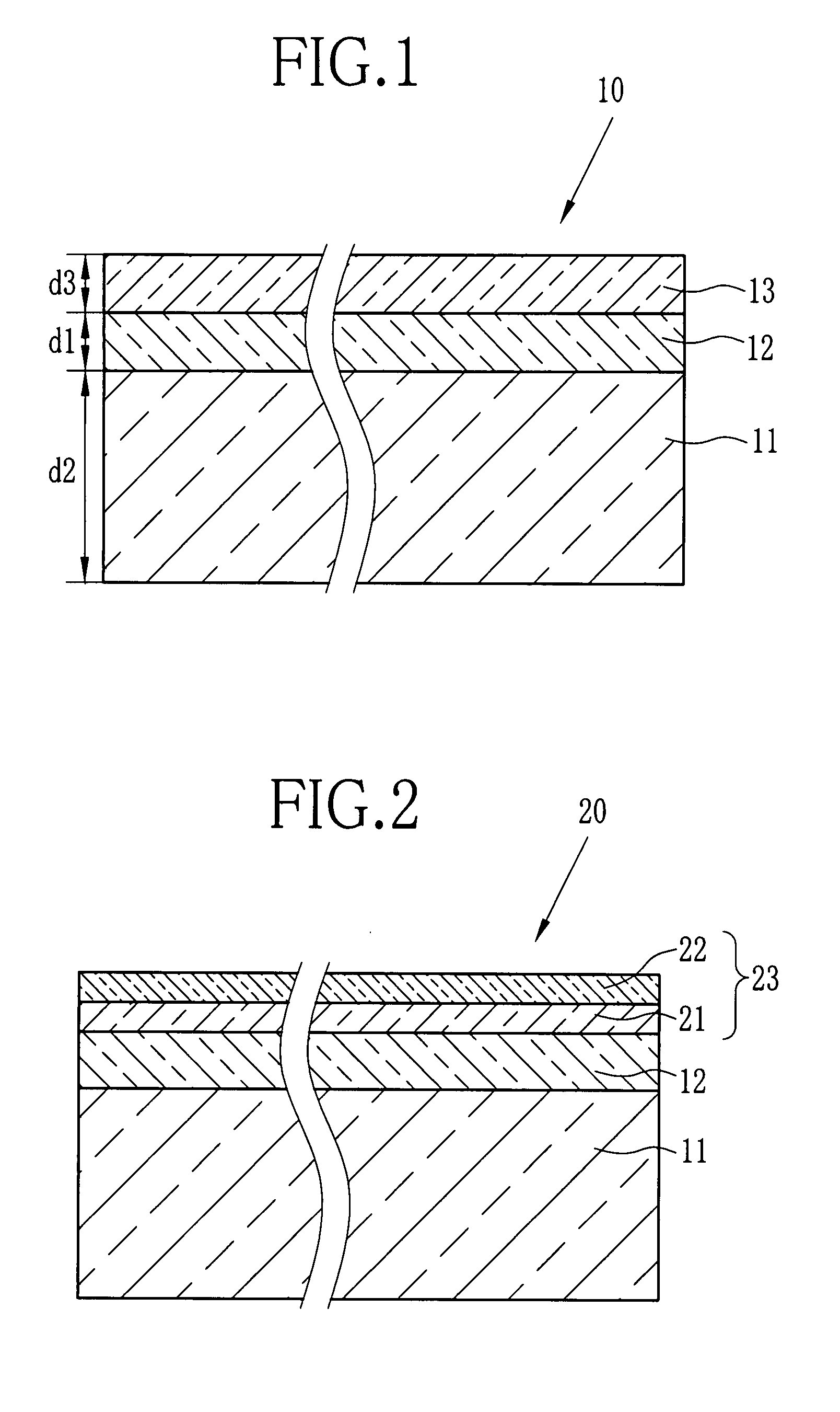
[0077]In this example, in accordance with the following procedure, the multi-layer film 10 shown in FIG. 1 was formed. Note that the second layer 13 has a single-layer structure composed of the hard coat layer 21 solely.

[0078][Base Material]

[0079]Polyethylene terephthalate (hereinafter referred to as PET) having inherent viscosity of 0.66 was synthesized by polycondensation reaction. The catalyst used in the reaction was antimony trioxide. The PET was dried until the water content thereof became less than 50 ppm, and thereafter melted in an extruder having a heater set at the temperature of 280 to 300° C. Next, the melted PET was discharged onto a chill roll to which electrostatic charge was applied from a die section, thus obtaining an amorphous film. Subsequently, the amorphous film was stretched 3.3 times in the longitudinal direction of the film, and further stretched 3.8 times in the width direction thereof, thus completing the biaxially stretching and producing the base materi...

example 2

[0090]A multi-layer film was formed in the same manner as example 1 except that zirconium oxide dispersion liquid was instead of the second fine particle dispersion liquid in the coating liquid A. The zirconium oxide dispersion liquid was zirconium oxide sol (product name: HZ-307W6, water solution with solid content of 20%, and produced by Nissan Chemical Industries, Ltd). The application amount of solid content was 189 (mg / m2). Furthermore, the thickness and refractive index of the first layer 12 corresponding to Example 2 were measured in the same manner as Example 1. The result was: η2=1.70 and d1=88 nm.

example 3

[0091]A multi-layer film was formed in the same manner as example 1 except that indium oxide dispersion liquid was used instead of the second fine particle dispersion liquid in the coating liquid A. The indium oxide dispersion liquid was EP ITO DL-1 (water solution with solid content of 20%, and produced by JEMCO INC.). The application amount of solid content was 170 (mg / m2). Furthermore, the thickness and refractive index of the first layer 12 corresponding to Example 3 were measured in the same manner as Example 1. The result was: η2=1.70 and d1=78 nm.


PUM

PropertyMeasurementUnit
refractive index η1aaaaaaaaaa
thickness d1aaaaaaaaaa

Abstract

A first layer containing a binder and fine particles having any one of tin oxide, indium oxide, zirconium oxide, and titanium oxide as a main component is formed at least on one surface of a base material formed of polyester in this order from a side of the base material. A second layer is disposed so as to be in contact with the first layer. Thereby, a multi-layer film is formed. When a refractive index of the base material is η1, that of the first layer is η2, and that of the second layer is η3, a formula denoted by η1<η2<η3 is satisfied. The multi-layer film has strong adhesive strength between layers, and exhibits excellent optical properties by efficiently preventing occurrence of rainbow unevenness due to interference of light on the interface. Further, the multi-layer film is used as a component of an image display device, thus ensuring excellent image quality.

Description

FIELD OF THE INVENTION[0001]The present invention relates to a multi-layer film, and an image display device such as a liquid crystal display (LCD), a plasma display (PDP), an organic electroluminescence display (organic EL display), surface-conduction electron-emitter display (SED), a cathode ray tube display (CRT display), or the like using the multi-layer film as its component.BACKGROUND OF THE INVENTION[0002]In accordance with an increase in demand for an image display device such as a LCD, a PDP, an organic EL display, a SED, and a CRT display, demand for an optical film as its main component has been rapidly increasing for the purpose of obtaining high-quality image thereof. The optical film is a film provided with various optical functions for achieving prevention of reflection of external light, enlargement of viewing angle, correction of optical unevenness, and the like.[0003]The optical film is generally a multi-layer film having a multi-layer structure composed of a base ...

Claims


Application Information

Patent Timeline
Patent Type & Authority Applications(United States)
IPC IPC(8): G02B1/10
CPCG02B1/115
Inventor KOBAYASHI, TAKASHIHATAKEYAMA, AKIRASUZUKI, KATSUYOSHINOMURA, TATSUYA
Owner FUJIFILM CORP
Why Eureka
Try Eureka