

Solid electrolytic capacitor and manufacturing method thereof
a technology of solid electrolyte capacitor and manufacturing method, which is applied in the direction of fixed capacitor details, casings/cabinets/drawers, electrical apparatus casings/cabinets/drawers, etc., can solve the problems of increased leakage current, fine portion short circuit, and stress concentration in the vicinity of the boundary, so as to facilitate the positioning of the element, reduce the resistance of the bonding portion, and facilitate the effect of bending work
- Summary
- Abstract
- Description
- Claims
- Application Information
AI Technical Summary
Benefits of technology
Problems solved by technology
Method used
Image

Examples
example 1
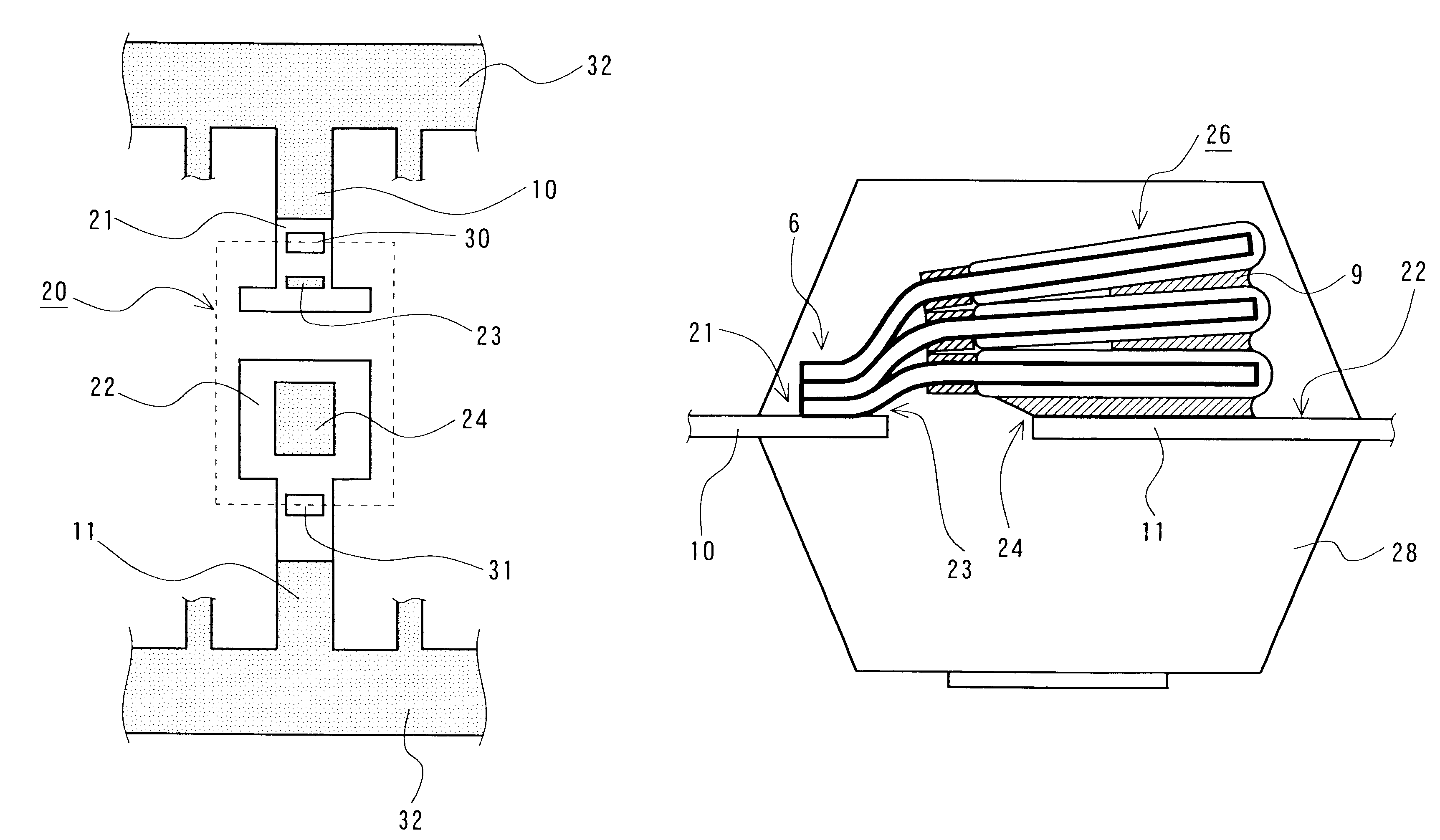
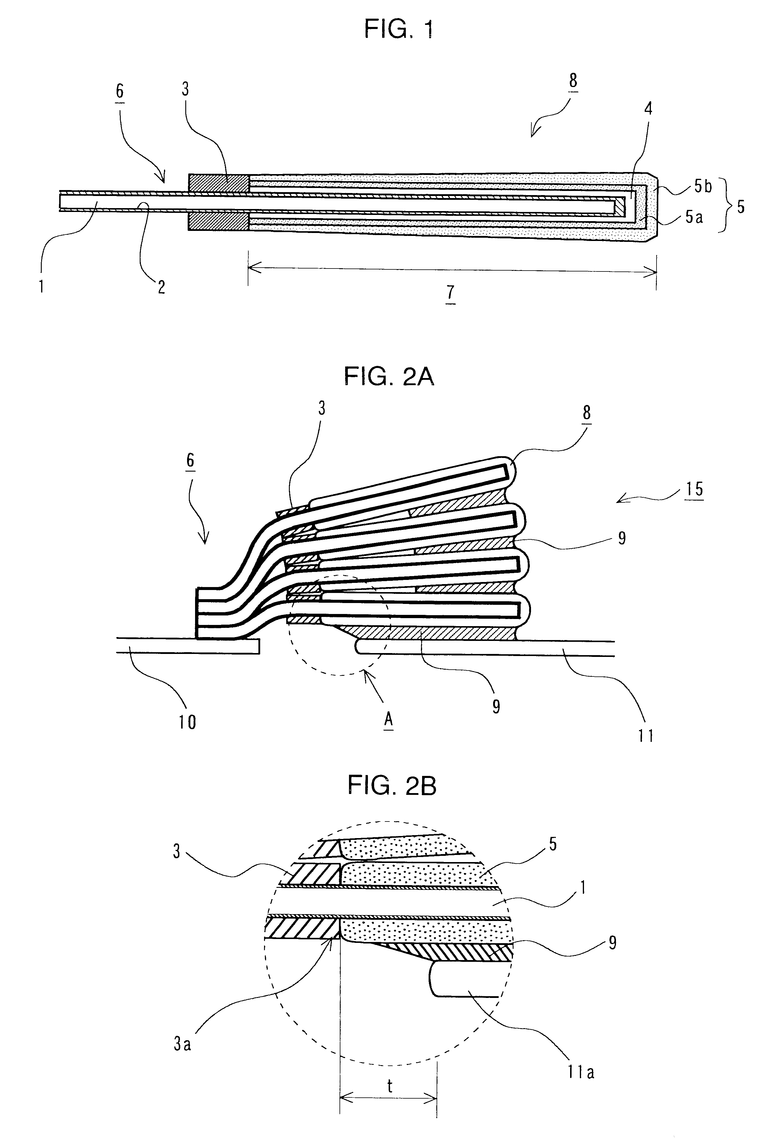
A single capacitor element (see FIG. 1) was manufactured as follows. An aluminum etched foil having on the surface thereof an alumina dielectric film was slit into a predetermined size of 90 .mu.m in thickness, 5 mm in length and 3 mm in width. This was used as a substrate (1). The anode was assigned to an end part (part of 1 mm in length and 3 mm in width) of the foil. An insulating layer (3) having a width of 1 mm was formed (circumferentially provided) thereon like a head-band so as to contact the anode part. The remaining part (3 mm in length.times.3 mm in width) was subjected to electrochemical forming with a 10 mass % aqueous ammonium adipate solution at 13 V to form a dielectric film (2) on the cut end parts (cutting plane). The resulting substrate was dipped in an aqueous solution prepared to have a composition such that ammonium persulfate was 20 mass % and sodium anthraquinone-2-sulfonate was 0.1 mass %, and then dipped in 1.2 mol / L of an isopropanol solution having dissol...
example 2
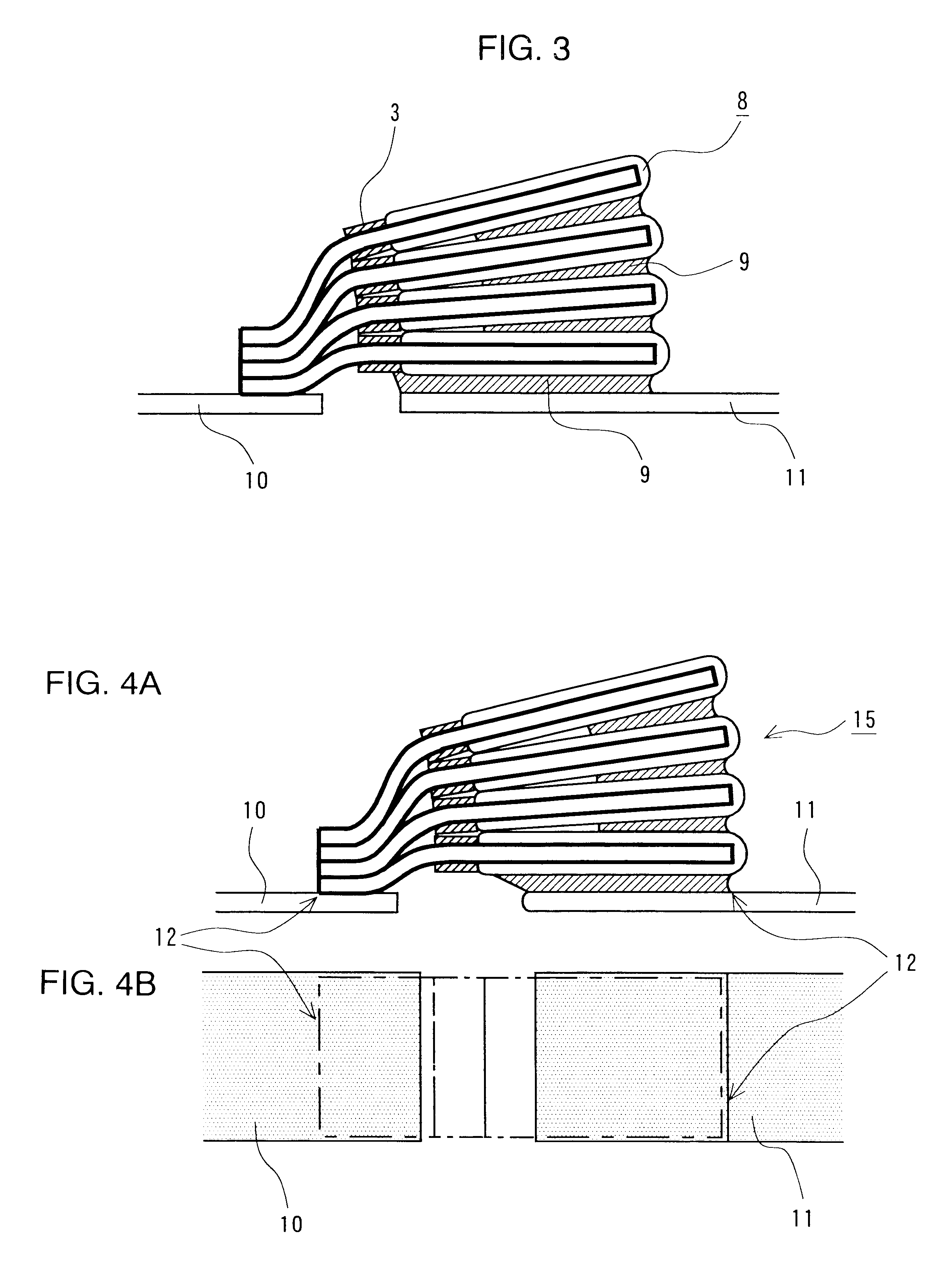
Capacitors were manufactured and evaluated in the same manner as in Example 1 except that the lead frame position was changed to 1.0 mm. The results obtained are shown in Table 1.
example 3
Capacitors were manufactured and evaluated in the same manner as in Example 1 except that the lead frame position was changed to 1.5 mm. The results obtained are shown in Table 1.
PUM
| Property | Measurement | Unit |
|---|---|---|
| thickness | aaaaa | aaaaa |
| thickness | aaaaa | aaaaa |
| length | aaaaa | aaaaa |
Abstract
Description
Claims
Application Information