Light diffusive sheet and area light source element using the same

a technology of light diffusive sheets and light sources, applied in mechanical devices, lighting and heating apparatus, instruments, etc., can solve the problems of narrow view angle, extremely decreased, and slightly off-front direction of light sources

Inactive Publication Date: 2003-09-18
KIMOTO CO LTD
View PDF11 Cites 16 Cited by
  • Summary
  • Abstract
  • Description
  • Claims
  • Application Information

AI Technical Summary

Problems solved by technology

However, although front luminance is increased in an area light source using an area light source element adopting such a downward-facing prism sheet, luminance in a direction slightly off the front direction (direction normal to the light-emitting surface of the light guide plate) is extremely decreased, resulting in a narrow view angle.
That is, a problem arises that directionality of outgoing light from the area light source ele

Method used


Image

  • Light diffusive sheet and area light source element using the same
  • Light diffusive sheet and area light source element using the same
  • Light diffusive sheet and area light source element using the same

Examples


example 1

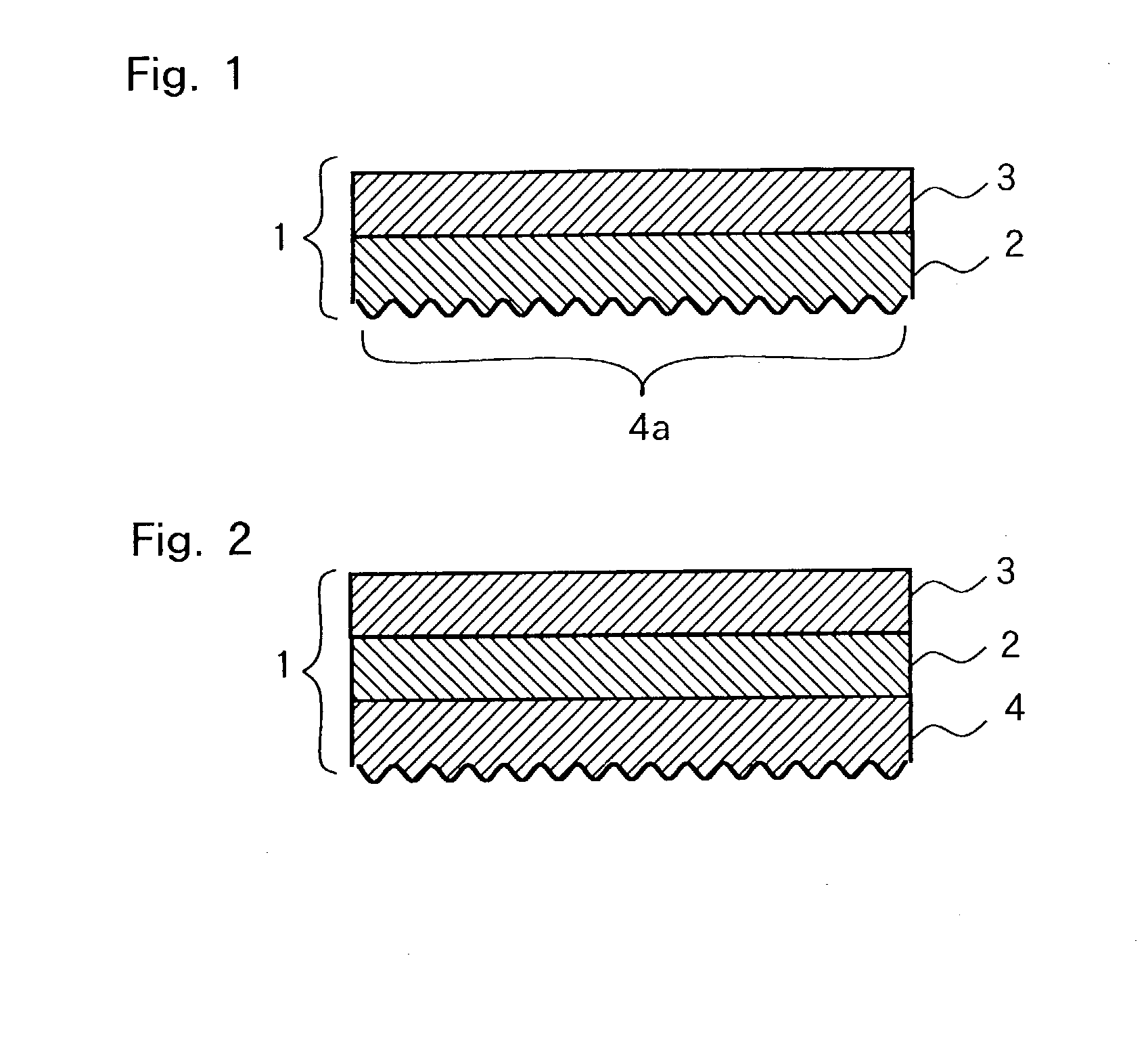
[0064] Coating solution (a) for backcoat layer having the following composition was applied to one surface of a transparent polyethylene terephthalate film (Lumirror T-60: Toray Industries Inc.) having a thickness of 100 .mu.m, and dried and cured with heat to form a backcoat layer having a thickness of about 4 .mu.m. Then, Coating solution (b) for light diffusion layer having the following composition was applied to the surface opposite of the backcoat layer, and dried and cured with heating to form a light diffusion layer having a thickness of about 12 .mu.m. Thus, a light diffusive sheet was produced.

1 Acrylic polyol 162 Parts (Acrydic A-807, solid content: 50%, Dainippon Ink and Chemicals, Inc.) Isocyanate 32 Parts (Takenate D110N, solid content: 60%, Mitsui Takeda Chemicals, Inc.) Polyethylene wax dispersion 30 Parts (solid content: 10%, mean particle diameter: .mu.m) Acrylic resin particles 0.5 Parts (Techpolymer MB30X-10SS, mean particle diameter: 10 .mu.m, Sekisui Plastics ...

example 2

[0066] A light diffusive sheet was produced in the same manner as in Example 1 except that Coating solution (c) for backcoat layer having the following composition was used instead of Coating solution (a) for backcoat layer of Example 1 to form a backcoat layer having a thickness of about 4 .mu.m.

3 Acrylic polyol 162 Parts (Acrydic A-807, solid content: 50%, Dainippon Ink and Chemicals, Inc.) Isocyanate 32 Parts (Takenate D110N, solid content: 60%, Mitsui Takeda Chemicals, Inc.) Polyethylene wax dispersion 30 Parts (solid content: 10%, mean particle diameter: 3 .mu.m) Acrylic resin particles 1 Part (Techpolymer MBX-8, mean particle diameter: 8 .mu.m, Sekisui Plastics Co., Ltd.) Butyl acetate 200 Parts Methyl ethyl ketone 200 Parts

examples 3 , 4

Examples 3, 4

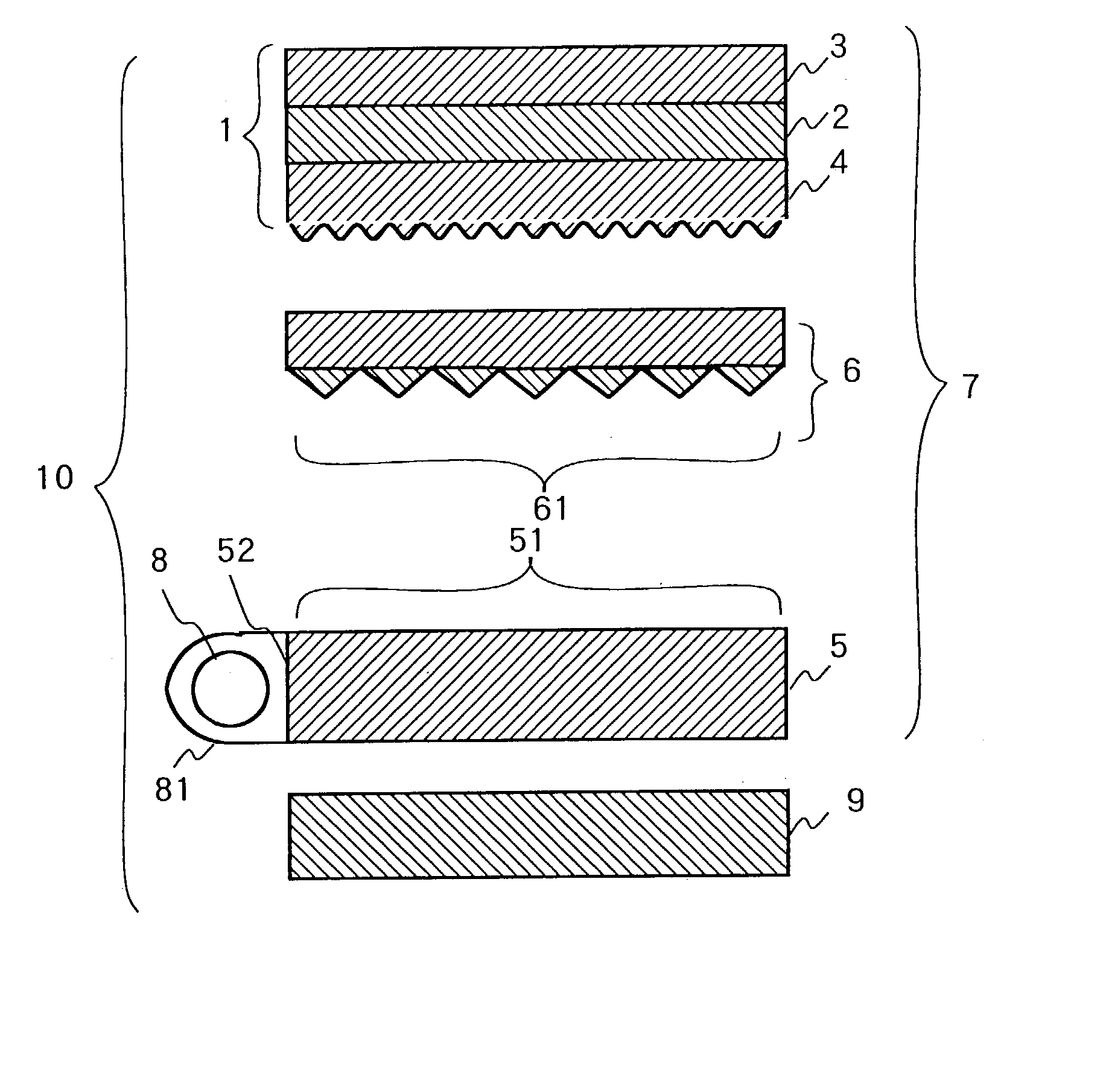
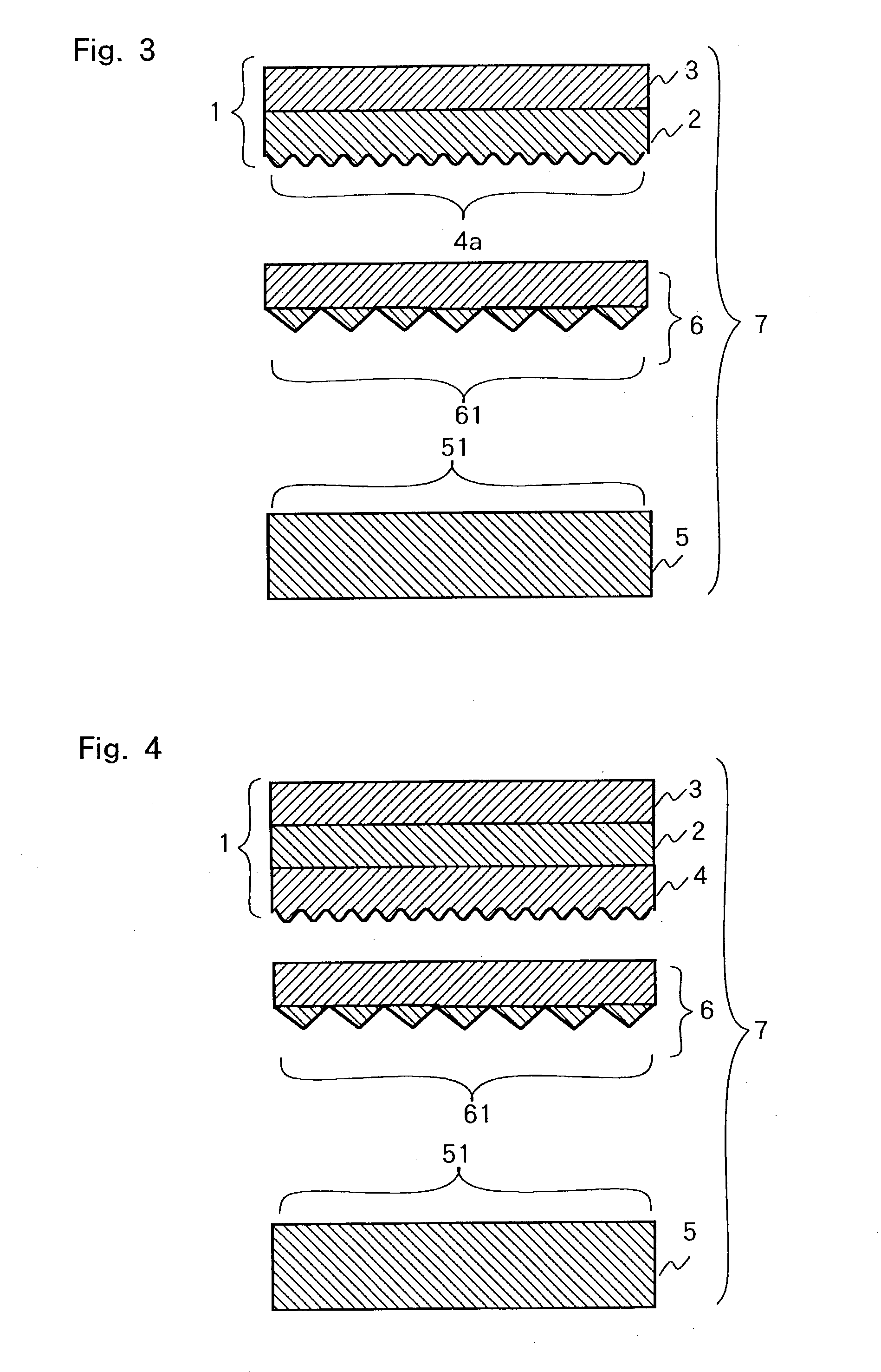
[0073] A prism sheet was laminated on the light-emitting surface of a light guide plate having a diagonal width of 13.3 inches (1 inch=25.4 mm) so that the prism surface should be opposed thereto, and the light diffusive sheet produced in Examples 1 or 2 was laminated on the surface of the prism sheet opposite of the prism surface so that the backcoat layer should be opposed thereto. Thus, area light source elements were produced.

[0074] Subsequently, a cold-cathode tube covered with a lamp reflector was disposed at one end surface of the light guide plate that was a light-incidence surface, and a light-reflecting member was disposed on the surface opposite of the light-emitting surface to obtain area light sources.


PUM


Abstract

A light diffusive sheet of the present invention comprises a transparent polymer sheet provided with a light diffusion layer 3 on one side and an uneven surface 4a having arithmetical mean deviation of 0.5 mum or less and mean spacing of 80 mum or narrower on the opposite side. Such an uneven surface can be made by forming a backcoat layer 4 including a mixture of particles having particular mean diameters in a particular proportion to a binder resin on the transparent polymer sheet. An area light source element 7 of the present invention is produced by laminating a prism sheet 6 on a light guide plate 5 so that the prism surface 61 of the prism sheet 6 is opposed to the light-emitting surface 51 of the light guide plate 5 and laminating the light diffusive sheet on the prism sheet 6 so that the uneven surface (backcoat layer) of the light diffusive sheet is opposed to the surface opposite of the prism surface. The light diffusive sheet of the present invention can prevent occurrence of a rainbow-like annular pattern without deteriorating the front luminance and view angle of the area light source even when combined with a downward-facing prism sheet.

Description

[0001] The present invention relates to an area light source element constituting an area light source suitably used for a liquid crystal display etc. and a light diffusive sheet suitably used as a member constituting the area light source element.RELATED ART[0002] Conventionally, an area light source called an edge-light type backlight has been used for a liquid crystal display etc.[0003] In general, in such an area light source, as shown in FIG. 6, a light-reflecting member 9 is laminated on a surface opposite of a light-emitting surface 51 of a light guide plate 5 equipped with a lamp such as a cold-cathode tube at least on one side surface 52, and a plurality of light-transmitting members such as light diffusive sheets 1 and prism sheets 6 are laminated on the light-emitting surface 51.[0004] In recent years, development of an area light source superior in so-called cost-performance is under study. Specifically, the number of these laminated light-transmitting members is reduced...

Claims


Application Information

Patent Timeline
IPC IPC(8): F21V3/04G02B5/02F21V5/00F21V8/00F21Y103/00G02B6/00G02F1/13357
CPCF21V3/04F21V5/00G02B6/0065G02B6/0053G02B6/0051G02F1/1335
Inventor TOSHIMA, YASUMAROTAKAI, MASASHINAGAMI, HIDEHARU
Owner KIMOTO CO LTD
Why Eureka
Try Eureka