Bowling ball abrader and polisher system and method

a polisher and bowling ball technology, applied in bowling games, carpet cleaning, vehicle cleaning, etc., can solve the problems of inconsistent results, lower scores, wear and scratching of the outer surface of the bowling ball during use, etc., and achieve consistent and reliable grip of the lane surface

Inactive Publication Date: 2011-02-22
SMANIA GARY L
View PDF14 Cites 24 Cited by
  • Summary
  • Abstract
  • Description
  • Claims
  • Application Information

AI Technical Summary

Benefits of technology

[0013]The concentric patterns formed using the present invention provide a more even surface on the bowling ball that is intended to result in a more consistent and reliable grip of the lane surface.

Problems solved by technology

The outer surface of a bowling ball is susceptible to wear and scratching during use, as it impacts, initially skids, and then rolls down the lane towards impact with the pins.
Such wear tends to be uneven, and the resulting unpredictable and irregular spin, as well as a loss of ‘trueness” while rolling produces inconsistent results and lower scores.
Commercial-grade refinishing equipment is available; however, many bowlers are reluctant to hand over their bowling balls to operators of questionable skill, and would prefer to abrade and polish their bowling balls themselves.
Unfortunately, this method usually results in uneven abrading and finishing, increasing the rolling problems of the ball.
In addition, the wear discussed above is subtle—at least with respect to the human eye, and it is essentially not possible for someone to hand polish a bowling ball to trueness where the bowling ball is held stationary.
There are two problems with this approach, the first is similar to the stationary-ball polishing method—uneven hand pressure results in uneven surface wear, which at best doesn't resolve the initial problem, and at worst, makes the ball unusable.
A second problem is familiar to users of machine sanders—if the user is not careful, the abrasive is continually applied to the same surface, resulting in unintentional, rapid surface wear that again results in a bowling ball that does not roll true.

Method used


Image

  • Bowling ball abrader and polisher system and method
  • Bowling ball abrader and polisher system and method
  • Bowling ball abrader and polisher system and method

Examples


Embodiment Construction

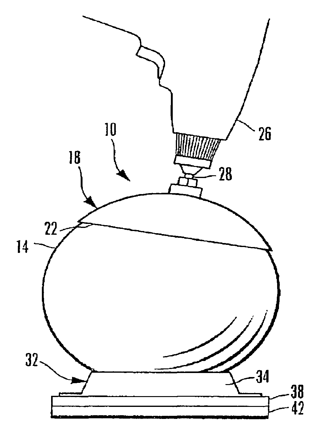
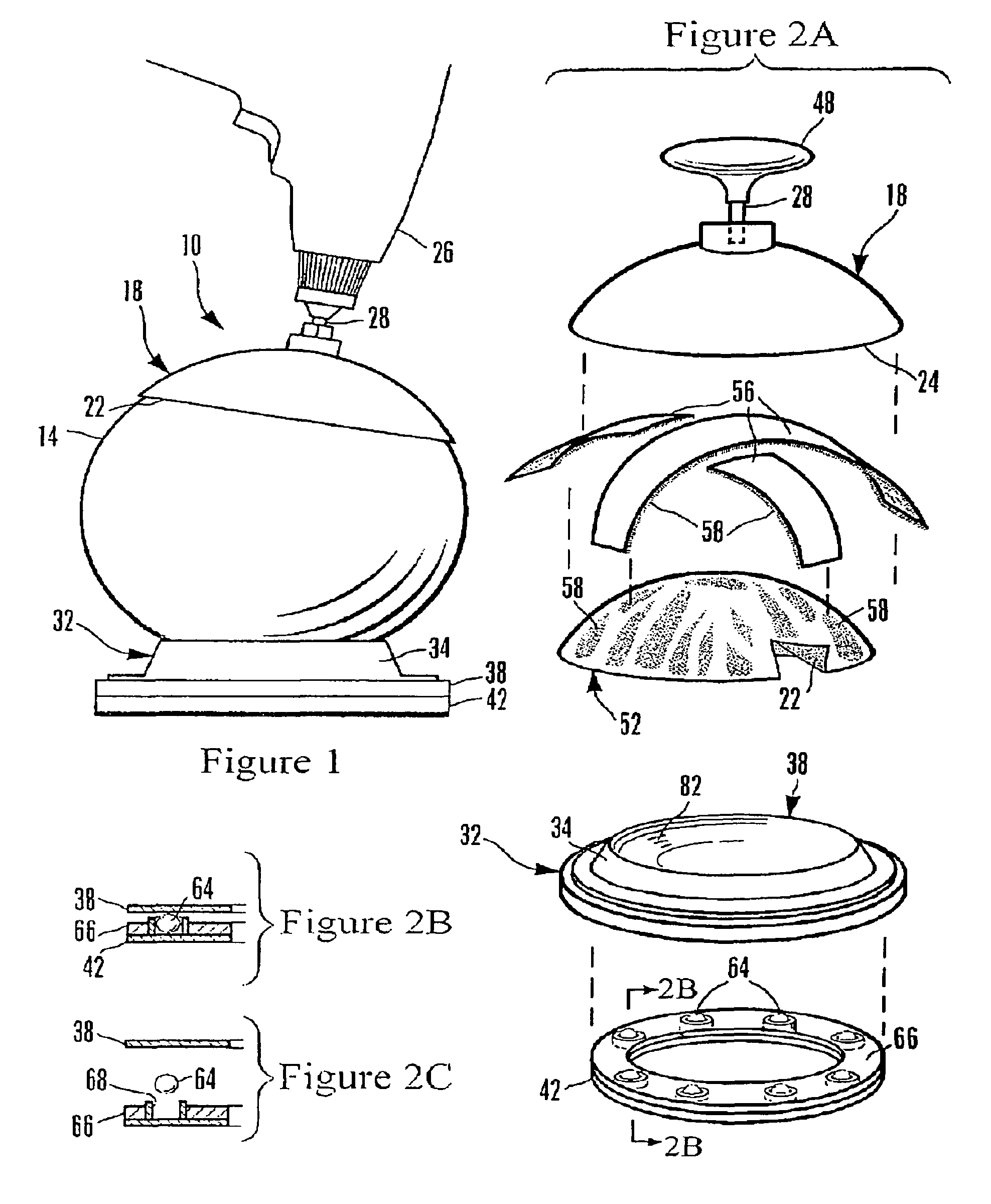
[0031]Reference is now made to the drawings wherein like numerals refer to like parts throughout. In FIG. 1, a powered abrader and polisher 10 is shown in use to repair surface defects in a bowling ball 14. A cup-shaped tool 18 utilizes an inner abrasive surface 22 formed within an inner cavity 24 (see FIG. 2A) of the cup-shaped tool 18 to remove surface detects from the bowling ball 14. A hand held power drill 26 attaches to the cup-shaped tool 18 using a centrally-located projecting shaft 28.

[0032]The bowling ball 14 is received by a non-motorized rotating ball holder assembly 32, that includes retaining cup holder 34 into which the bowling ball 14 is placed. The cup holder 34 is attached to (or is formed as part of) a rotatable top case 38, which is in turn supported by a stationary base 42 that rests against a support surface (not shown) for the powered abrader and polisher 10.

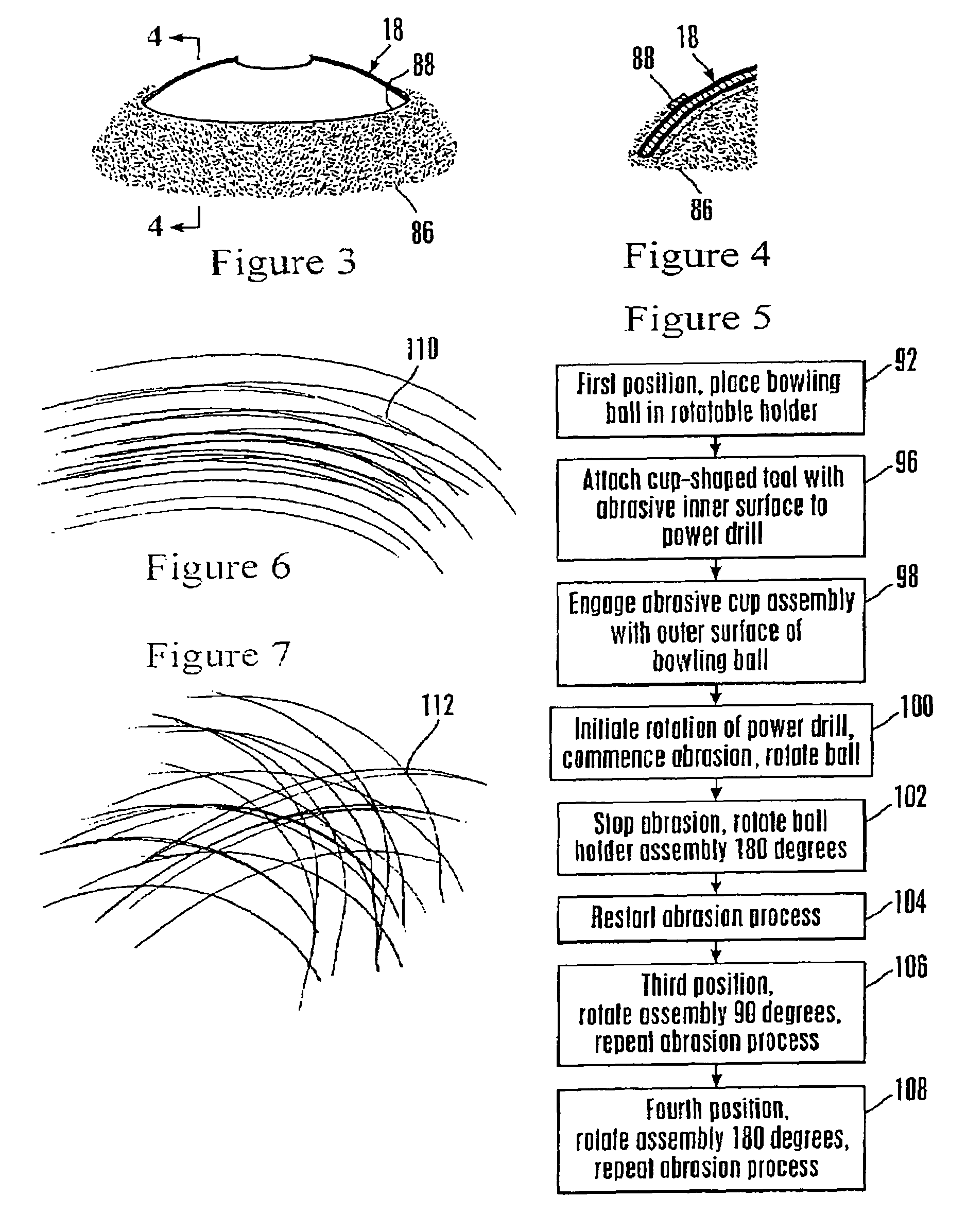
[0033]When relatively minor surface treatment is required the cup-shaped tool 18 can be adapted for use...


PUM

PropertyMeasurementUnit
diameteraaaaaaaaaa
diameteraaaaaaaaaa
curvatureaaaaaaaaaa

Abstract

A bowling ball abrader and polisher utilizes cooperative rotational inter-engagement between a cup-shaped abrading an polishing tool and a non-motorized rotating ball holder assembly to obtain even, concentric abrasion patterns on a bowling ball surface. Upon placement of a bowling ball in a ball cradling surface formed in the rotating ball holder, application of the rotating abrading and polishing tool on the surface of the bowling ball causes a corresponding rotation of the bowling ball using the non-motorized rotating ball holder, which enables the outer surface of the bowling ball to be more uniformly abraded and polished.

Description

RELATED APPLICATIONS[0001]The present application claims priority under 35 U.S.C. 119(e) to U.S. Provisional Patent Application, Ser. No. 61 / 143,894, filed Jan. 12, 2009, which is incorporated by reference herein.BACKGROUND OF THE INVENTION[0002]1. Field of the Invention[0003]The present invention relates to abrading and polishing tools and, more particularly, to such tools as are useful for refinishing a surface on a bowling ball. More specifically, the present invention relates to a tool assembly for abrading and polishing the outer surface of a bowling bail.[0004]2. Description of the Related Art[0005]The outer surface of a bowling ball is susceptible to wear and scratching during use, as it impacts, initially skids, and then rolls down the lane towards impact with the pins. Such wear tends to be uneven, and the resulting unpredictable and irregular spin, as well as a loss of ‘trueness” while rolling produces inconsistent results and lower scores. Casual bowlers may not even noti...

Claims


Application Information

Patent Timeline
Patent Type & Authority Patents(United States)
IPC IPC(8): B24B1/00B24B23/02
CPCB24B11/10
Inventor SMANIA, GARY LOUISBRANDT, JOHN M.
Owner SMANIA GARY L
Why Eureka
Try Eureka