Pushup apparatus

a push-up and push-up technology, applied in the field of physical fitness, can solve the problems of excessive drag, user's inability to complete proper biomechanics, and the dependence of sliding hand grips on each other, so as to increase the use of the stabilizing core/trunk muscles of the user, increase/maximize the range of motion, and strengthen the upper body

Inactive Publication Date: 2011-02-22
BECKFORD TYSON
View PDF17 Cites 48 Cited by
  • Summary
  • Abstract
  • Description
  • Claims
  • Application Information

AI Technical Summary

Benefits of technology

[0010]The present invention is a pushup apparatus used to strengthen the upper body. With the user in the prone position horizontal to the floor, the user raises the upper body up off of the ground by pushing upward and inward against the grips with their hands. The trunk of the body remains straight throughout the exercise and feet / toes remain on the ground. The grips move free and independent of each other along the elongated bar. The elongated bar defines the path of motion of the handgrips. This free and independent motion allows the user to perform a converging pushup while increasing the use of the stabilizing core / trunk muscles of the user. The converging motion toward the midline allows for the chest muscles to increase / maximize the range of motion over the traditional pushup exercise done without the apparatus.

Problems solved by technology

However, to the best of the inventor's knowledge, there is no pushup apparatus that combines an independent sliding / converging motion with the use of linear bearings and a segmented bar that has the ability of the hand grips to spin freely around the axis of its stationary bar allowing for forearm development as well as the benefits of a converging pushup exercise.
The disadvantage is the user does not complete the proper biomechanics during the range of motion of the exercise.
The disadvantage of the Jeneve apparatus is that the sliding hand grips are dependent upon each other.
The disadvantage is that the sliding members are designed to be locked in various positions to create a static / non lateral movement during the exercise.
If the apparatus is unlocked, it will create excessive drag during the exercise do to the user's body weight being forced down vertically pressing the members against the base.

Method used


Image

  • Pushup apparatus
  • Pushup apparatus
  • Pushup apparatus

Examples


Embodiment Construction

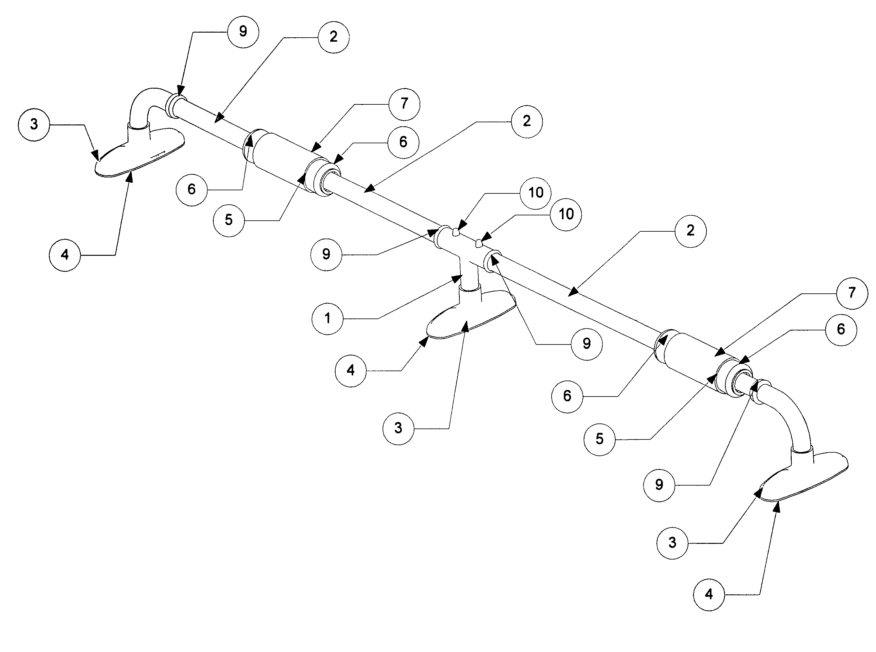
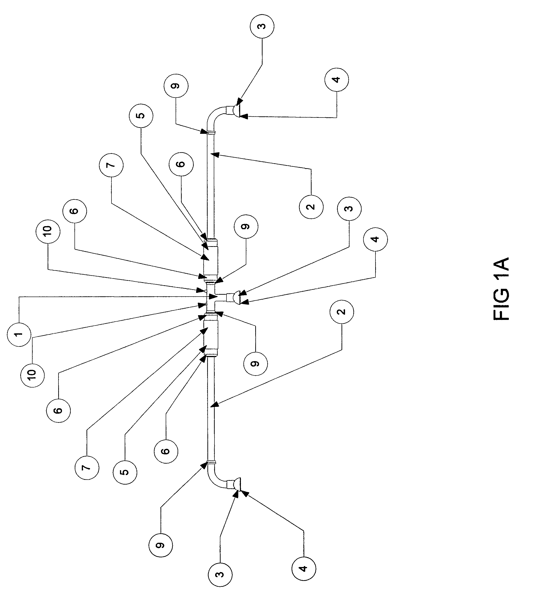
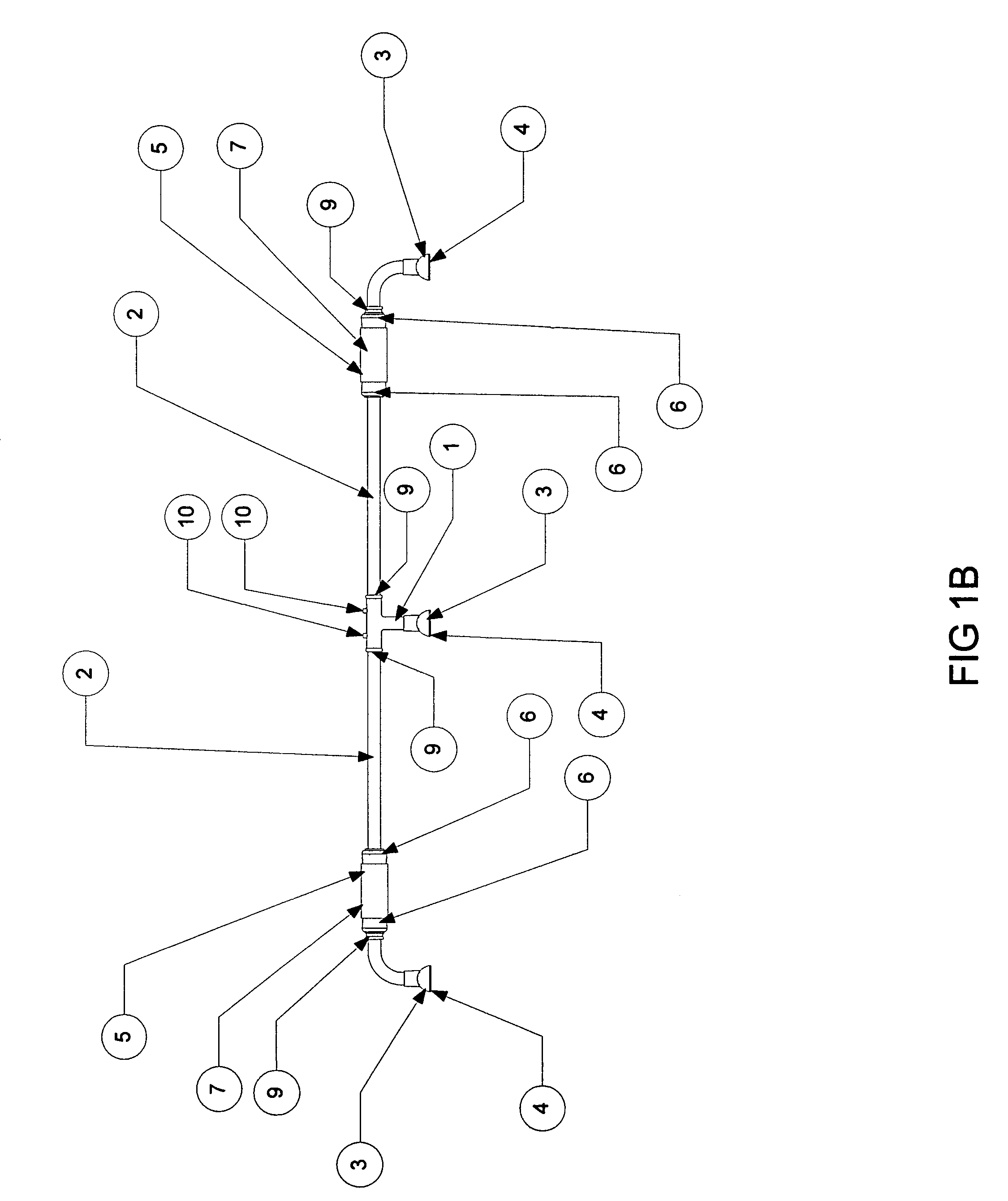
[0024]Referring now to the invention in more detail, in (FIGS. 1A & 1B), there is shown a front view of the assembled pushup apparatus, having a center T-Tube (1) and a right and left side Slide Tube (2). The right and left side Slide Tube will each contain a medial and lateral Stop Ring (9). The T-Tube (1) will have a hole / knotch on both the right and left side that will receive a Locking Pin Assembly (10) from both the right and left Slide Tube (2) when connected (FIG. 5). The T-Tube and right and left side Slide Tube (2) insert into a Foot (3). The Foot (3) is finished with a Foot Grip (4). The right side Slide Tube (2) has a Handle (5), Handle Cap (6), and Handle Grip (7) assembly (FIG. 10) that moves freely and independent along the linear path of the right side Slide Tube (2) between its respective medial and lateral Stop Rings (9). The left side Slide Tube (2) has a Handle (5), Handle Cap (6), and Handle Grip (7) assembly (FIG. 10) that moves freely and independent along the ...


PUM


Abstract

A pushup apparatus having a centered T-Tube, right and left Slide Tube, a medial and lateral Stop Ring located on each Slide Tube. The T-Tube will contain a hole / knotch on both the right and left side that will receive the Locking Pin Assembly from the corresponding right and left Slide Tube. The T-Tube and Slide Tubes will insert into a Foot and the Foot will be finished with a Foot Grip. The right side Slide Tube has a Handle, Handle Cap, Handle Grip assembly that moves freely and independent along the linear path of the right side Slide Tube between its respective medial and lateral Stop Rings. The left side Slide Tube has a Handle, Handle Cap, Handle Grip assembly that moves freely and independent along the linear path of the left side Slide Tube between its respective medial and lateral Stop Rings. The free independent motion will be achieved by use of Linear Bearing Assemblies. The Linear Bearing Assembly is affixed within the Handle, Handle Cap, Handle Grip assembly. The free and independent movement forces the user to create the symmetry during the movement of the exercise, thus engaging the stabilizer muscles of the bodies trunk. The right and left Slide Tube will have a Locking Pin Assembly at their medial ends that will connect to holes / knotches in the T-Tube.

Description

[0001](This application claims the benefit of U.S. Provisional Application No. 61 / 008,846 filed Dec. 26, 2007)CROSS-REFERENCE TO RELATED APPLICATIONS[0002]Not ApplicableSTATEMENT REGARDING FEDERALLY SPONSORED RESEARCH OR DEVELOPMENT[0003]Not ApplicableREFERENCE TO SEQUENCE LISTING, A TABLE, OR A COMPUTER PROGRAM LISTING COMPACT DISK APPENDIX[0004]Not ApplicableBACKGROUND OF THE INVENTION[0005]The present invention is in the technical field of physical fitness / More particularly, the present invention is in the technical field of the pushup exercise / More particularly, the present invention is in the technical field of pushup apparatus.[0006]There are several types of existing pushup apparatus known in the prior art. However, to the best of the inventor's knowledge, there is no pushup apparatus that combines an independent sliding / converging motion with the use of linear bearings and a segmented bar that has the ability of the hand grips to spin freely around the axis of its stationary...

Claims


Application Information

Patent Timeline
Patent Type & Authority Patents(United States)
IPC IPC(8): A63B71/00
CPCA63B21/4017A63B23/1236
Inventor VARGA, THOMAS A.
Owner BECKFORD TYSON
Why Eureka
Try Eureka