Membrane support for drip chamber

a technology of membrane support and drip chamber, which is applied in the field of drip chambers, can solve the problems of membrane being sensitive and easily affected, affecting the whole purpose of the membrane drip chamber, and affecting the flow rate of the membrane, so as to achieve the effect of a larger surface area

Inactive Publication Date: 2011-02-22
KRAUS GMBH
View PDF4 Cites 87 Cited by
  • Summary
  • Abstract
  • Description
  • Claims
  • Application Information

AI Technical Summary

Benefits of technology

[0009]The present invention seeks to provide an improved membrane support that permits safe mounting of a membrane, e.g., a hydrophilic or bacterially retentive membrane, into a drip chamber with no danger of contaminating or ruining the membrane with adhesive and the like. The membrane support includes a support member that supports the membrane at a safe distance from ends of the support member which are bonded to the drip chamber with adhesive, or by friction. The seal between the membrane support and the drip chamber prevents direct fluid communication between the volume upstream of the membrane and the drip chamber outlet. Only liquid permeating through the membrane may reach the outlet. In one embodiment, the membrane is generally perpendicular to a longitudinal axis of the drip chamber. In another embodiment, the membrane is generally parallel to the longitudinal axis. The latter embodiment permits using a membrane with a significantly larger surface area and is particularly useful for a bacterially retentive membrane. The drip chamber may be constructed such that liquid may be in contact with the membrane even when the drip chamber may be oriented upside down.

Problems solved by technology

Membranes are sensitive structures and may easily be affected by solvents, glues and other bonding means.
However, this device has a drawback of the membrane being situated close to a base which is bonded with an adhesive to a drip chamber, meaning that the membrane can possible come into contact with the adhesive.
In addition, the structure of the membrane support is such that air entrapped downstream of the membrane between the membrane and drip chamber outlet, can occasionally escape into the infusion line, thus defeating the whole purpose of the membrane drip chamber.

Method used


Image

  • Membrane support for drip chamber
  • Membrane support for drip chamber
  • Membrane support for drip chamber

Examples


example 1

[0045]Gravitational Flow Rate

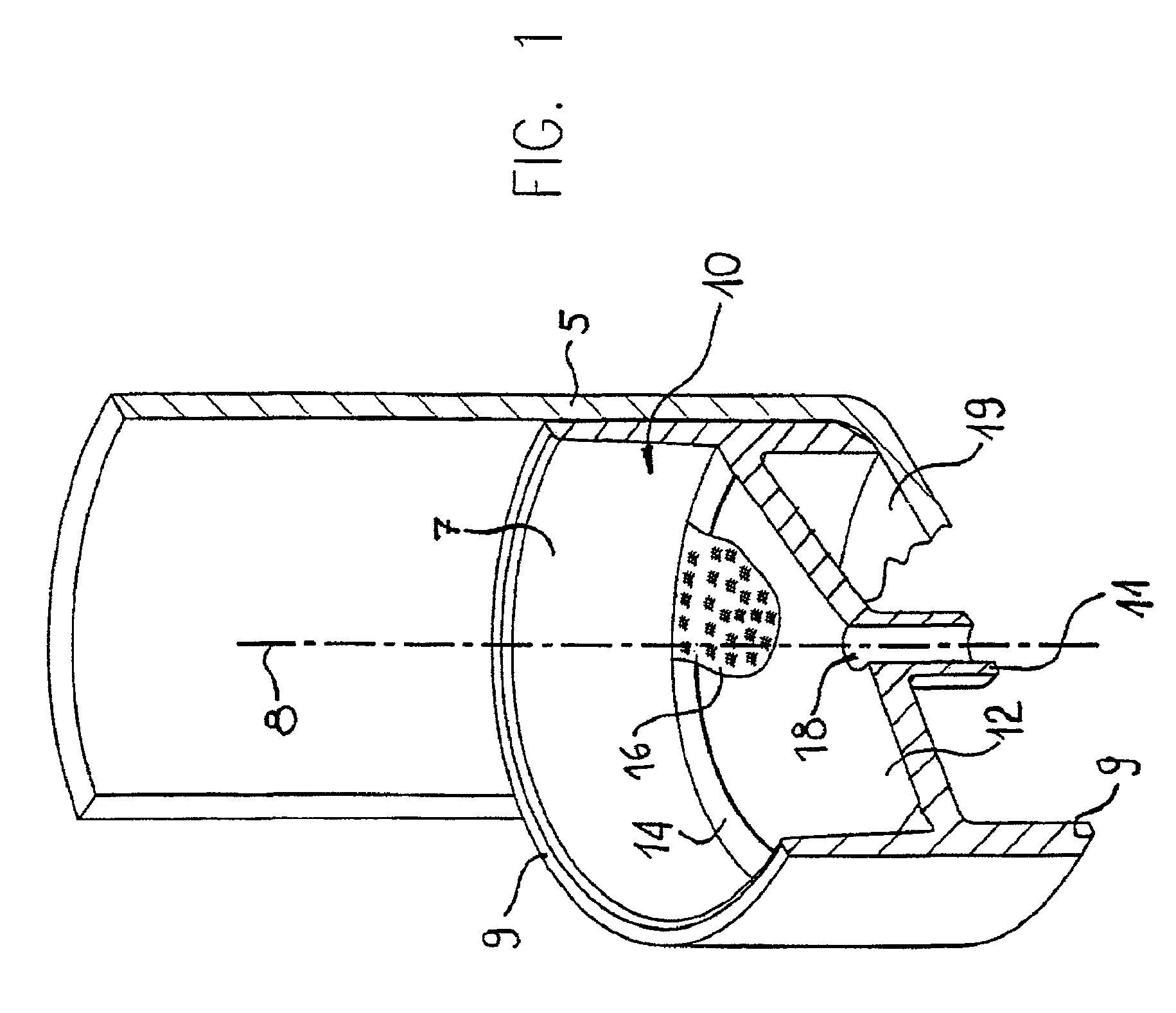
[0046]A membrane-containing drip chamber (MDC) was constructed in accordance with the embodiment of FIG. 1. An 8 μm rated nitrocellulose membrane was welded into the cylindrical insert. The MDC was incorporated in a standard infusion set. The gravitational flow rate was measured by connecting the set to an infusion bag containing saline and setting the outlet 1 m below the bag.

[0047]Flow rate ranged between 125 ml / min and 160 ml / min. The rate remained above 100 ml / min after 5 months of aging at 50° C. This rate conforms to International Standard for Infusion Equipment ISO 8536-4 (1998).

[0048]In order to test prevention of air intrusion, the set was opened to the atmosphere. No air leaked into the downstream line for at least 8 hours.

example 2

[0049]Bacterial Challenge

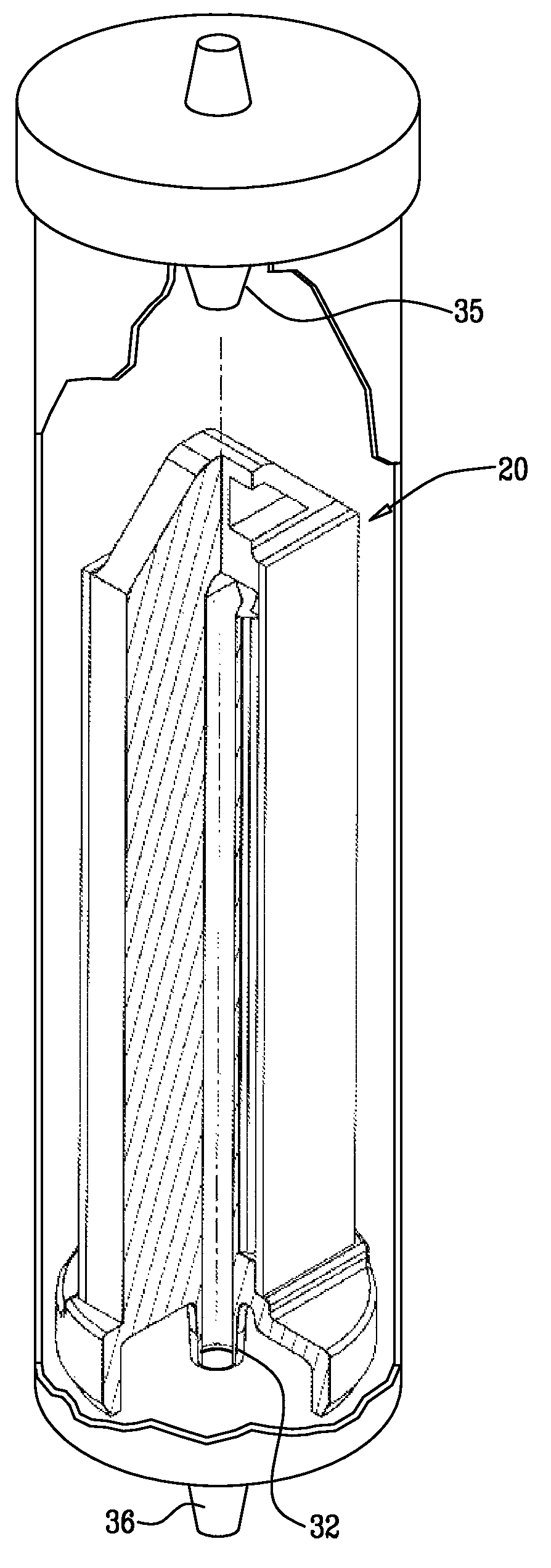
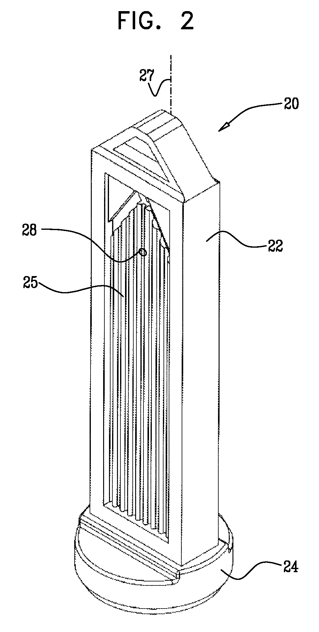
[0050]An MDC was constructed in accordance with the embodiment of FIGS. 2 and 3, using a 0.2 μm rated polysulfone membrane. Minimum bubble point was measured by incorporating the drip chamber in an infusion set, priming it with saline and allowing excess liquid to drain by gravity. The MDC with wetted membrane was then pressurized by air to 2 atm. No air was detected at the outlet, indicating a bubble point higher than 2 atm. The MDC was then challenged with a bacteria suspension by aseptically connecting the set to an infusion bag containing sterile saline. An inoculum of pseudomonas diminuta was injected through the injection site so that the final concentration was 106 CFU / ml. The whole bag (100 ml) was then drained through the MDC into an empty, sterile bag. The receiving bag was then tested for sterility. No CFU's were detected.


PUM

PropertyMeasurementUnit
surface areaaaaaaaaaaa
pore sizeaaaaaaaaaa
pressureaaaaaaaaaa

Abstract

A drip chamber for intravenous infusion including a support member having a longitudinal axis, two ends and at least one support face distanced from both ends, a membrane joined to the at least one support face, and a support member outlet formed in the support member and in fluid communication with the membrane, the support member outlet including a bore and being fluidly communicable with an outlet of the drip chamber.

Description

CROSS RELATION TO OTHER APPLICATIONS[0001]This application is a continuation-in-part of U.S. patent application Ser. No. 10 / 152,004, filed May 22, 2002, now abandoned and claims priority therefrom.FIELD OF THE INVENTION[0002]The present invention relates generally to drip chambers used with intravenous infusion sets and particularly to membrane supports for such drip chambers.BACKGROUND OF THE INVENTION[0003]Intravenous infusion sets commonly include drip chambers (DCs) to enable the flow rate of an infusion liquid to be visually observed. In a typical installation, an infusion bag is suspended above a patient and a spike at an inlet of the DC pierces the bag, whereby the infusion liquid drips into the DC. The flow rate of the infusion liquid may be observed by the rate of formation of drops of the liquid from the inlet into the DC down through an outlet of the DC which is connected to tubing to the patient. The DC helps prevent air from entering the downstream tubing. This is achie...

Claims


Application Information

Patent Timeline
Patent Type & Authority Patents(United States)
IPC IPC(8): A61M1/00A61M5/14A61M5/165A61M5/38
CPCA61M5/1411A61M5/165A61M5/38A61M2005/1657A61M2205/7518B29L2031/753B29C65/02B29C66/1222B29C66/1224B29C66/5346B29C66/612B29C66/73171B29C65/08
Inventor KRAUS
Owner KRAUS GMBH
Why Eureka
Try Eureka