Electric motor with discrete circuit board and sensor case

a technology of discrete circuit boards and motors, applied in the field of electric motors, can solve the problems of reducing the detection accuracy of the rotational position of the rotor, reducing the mounting accuracy of the hall elements, and reducing the dimensional accuracy of the mounting portion of each element, so as to achieve the effect of easy mounting, easy and accura

Inactive Publication Date: 2011-02-22
KK TOSHIBA +2
View PDF14 Cites 16 Cited by
  • Summary
  • Abstract
  • Description
  • Claims
  • Application Information

AI Technical Summary

Benefits of technology

[0006]The magnetism detecting circuit can easily be mounted on the terminal block since the magnetism detecting circuit comprises the circuit board. Furthermore, the rotation sensor can be positioned via the sensor case relative to the terminal block easily and accurately only when the circuit board is provided in the terminal block.

Problems solved by technology

In the above-described method, however, shrinkage of resin after the primary formation sometimes reduces dimensional accuracy of each element mounting portion.
Reduction in the dimensional accuracy of each element mounting portion results in reduction in the mounting accuracy of the Hall elements, thereby reducing a detection accuracy of rotational position of the rotor.

Method used


Image

  • Electric motor with discrete circuit board and sensor case
  • Electric motor with discrete circuit board and sensor case
  • Electric motor with discrete circuit board and sensor case

Examples


Embodiment Construction

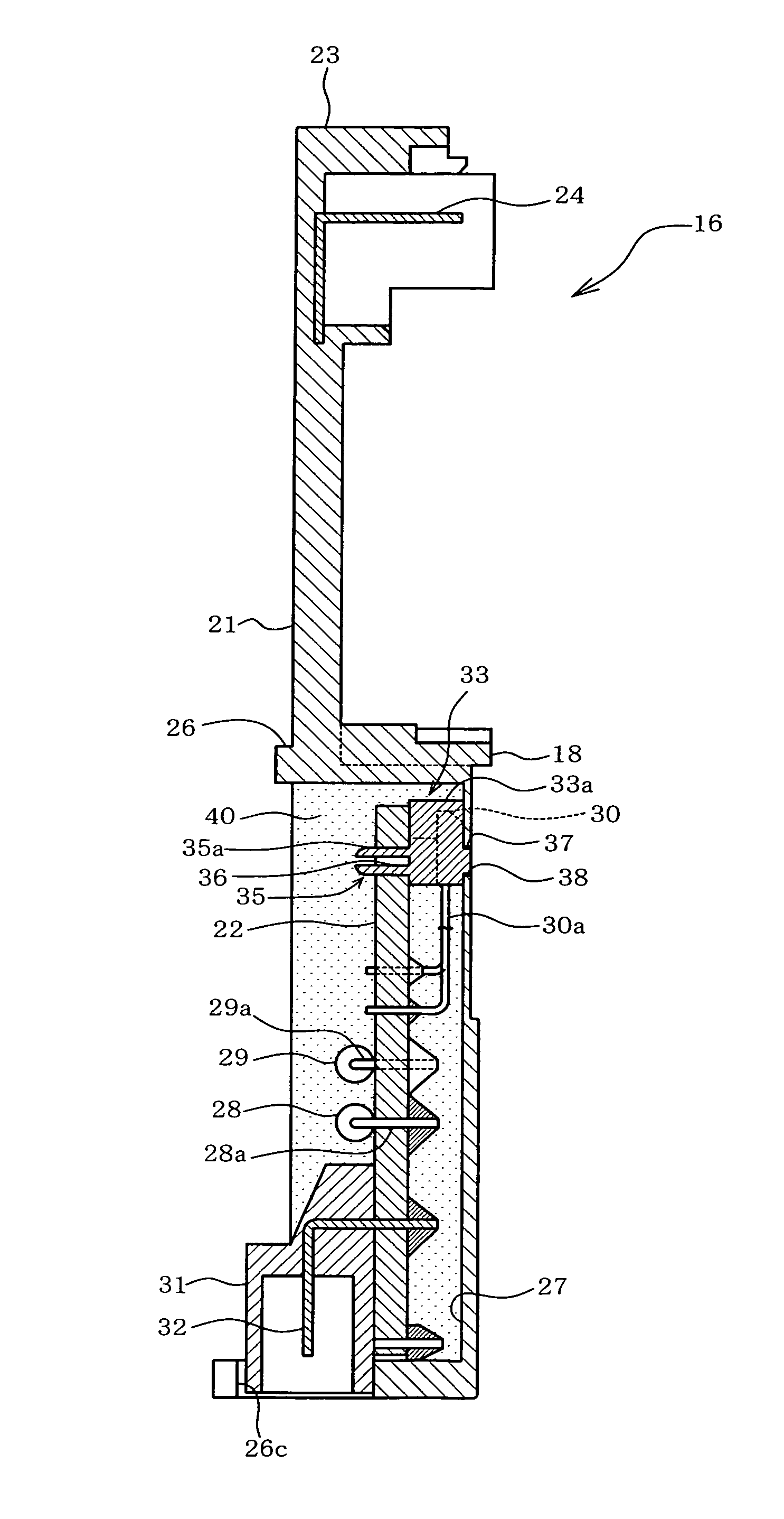
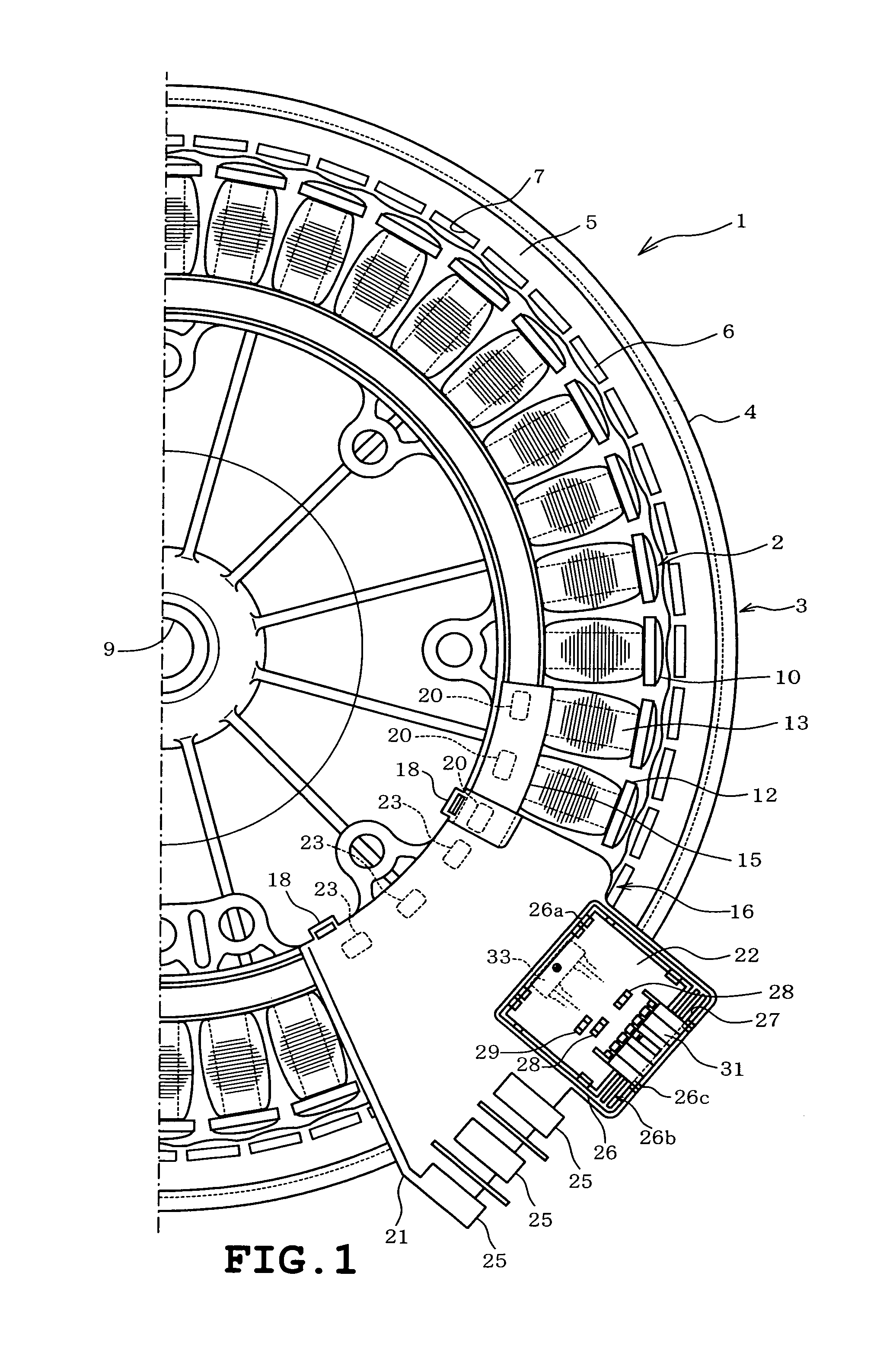
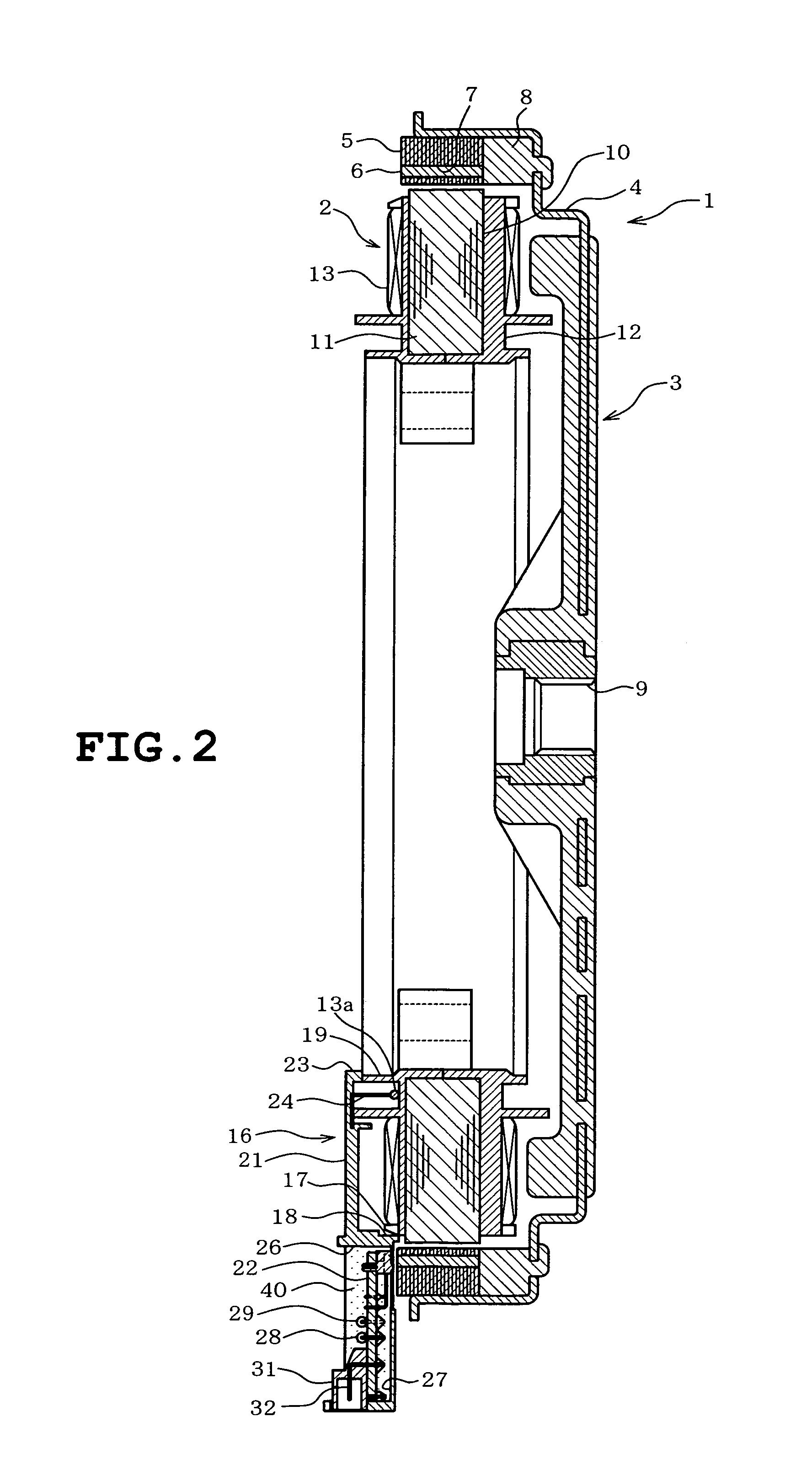
[0013]The invention will be described in more detail with reference to the accompanying drawings. FIGS. 1 to 6 illustrate one embodiment in which the invention is applied to a DC brushless motor of the outer rotor type for driving a rotating tub of a washing machine, for example.

[0014]Referring to FIGS. 1 and 2, the motor 1 of the embodiment comprises a stator 2 and a rotor 3. The rotor 3 includes a frame 4 made from a magnetic material into the shape of a shallow dish, an annular rotor core 5 disposed along an inner circumferential surface of a circumferential wall of the frame 4, and magnetic field permanent magnets 6 disposed on the inner circumference of the rotor core 5. Magnet insertion holes 7 are provided in the inner circumference of the rotor core 5. The magnetic field permanent magnets 6 are inserted in the magnet insertion holes 7 respectively. The rotor core 5, the magnetic field permanent magnets 6 and the frame 4 are integrated by molded resin 8 (shown only in FIG. 2)...


PUM


Abstract

An electric motor includes a rotor having a field permanent magnet, a board housing member fixed to a stator, and a magnetism detecting circuit that detects the magnetism of the field permanent magnet. The magnetism detecting circuit includes a circuit board that is discrete from the board housing member, a sensor case that is discrete from the circuit board and is supported on the circuit board, and a rotation sensor held by the sensor case. The board housing member has an engagement hole and a positioning surface. The sensor case has an engagement convexity corresponding to the engagement hole and an abutting surface corresponding to the positioning surface. When the circuit board has been located in the board housing member, the engagement convexity engages the engagement hole and the abutting surface abuts the positioning surface, resulting in that the rotation sensor is positioned relative to the board housing member.

Description

TECHNICAL FIELD[0001]The present invention relates to an electric motor provided with a rotation sensor detecting a rotational position of a rotor.BACKGROUND ART[0002]Electric motors include a type in which motor coils are connected via an insulating terminal block to an external circuit. In this type of motor, a rotational position detecting circuit is provided integrally in the terminal block so that efficiency in assembly of the terminal block to the motor is improved. In this case, Hall elements serving as a rotation sensor and a heat sensitive element serving as a temperature sensor are fitted into element mounting portions after an electrically conductive plate has been formed by insert molding in the forming of the terminal block. A secondary formation is then carried out so that the rotational position detecting circuit is formed integrally. Japanese Patent No. 3497684 discloses an electric motor constructed as described above, for example.DISCLOSURE OF THE INVENTIONProblem ...

Claims


Application Information

Patent Timeline
Patent Type & Authority Patents(United States)
IPC IPC(8): H02K11/00H02K29/06H02K29/00H02K29/08H02K3/52H02K5/22
CPCH02K3/522H02K29/08H02K5/225H02K11/215H02K21/22H02K2211/03
Inventor HAYASHI, KINYASHIGA, TSUYOSHIKIKUCHI, NAOTO
Owner KK TOSHIBA
Why Eureka
Try Eureka