Eureka AIR delivers breakthrough ideas for toughest innovation challenges, trusted by R&D personnel around the world.

Flow-through, inlet-gas-temperature-controlled, solvent-resistant, thermal-expansion compensated cell for light spectroscopy

a flow-through, light spectroscopy technology, applied in the field of optical cells, can solve the problems of prior optical cells not allowing the placement of ready samples in sample space, inability to adjust the optical path length within the cell, and inability to mitigate the linear expansion effect of prior optical cells, etc., to achieve fast kinetic processes, easy and inexpensive setting, and spectroscopic stability

Inactive Publication Date: 2011-02-22
GOVERNMENT THE
View PDF18 Cites 10 Cited by
  • Summary
  • Abstract
  • Description
  • Claims
  • Application Information

AI Technical Summary

Benefits of technology

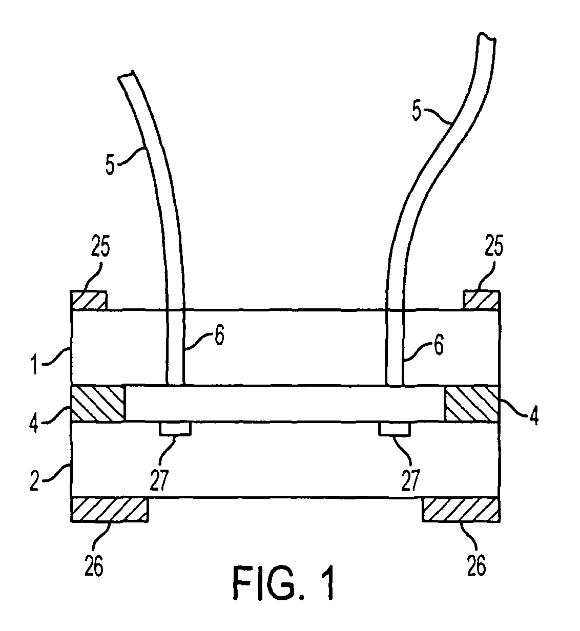
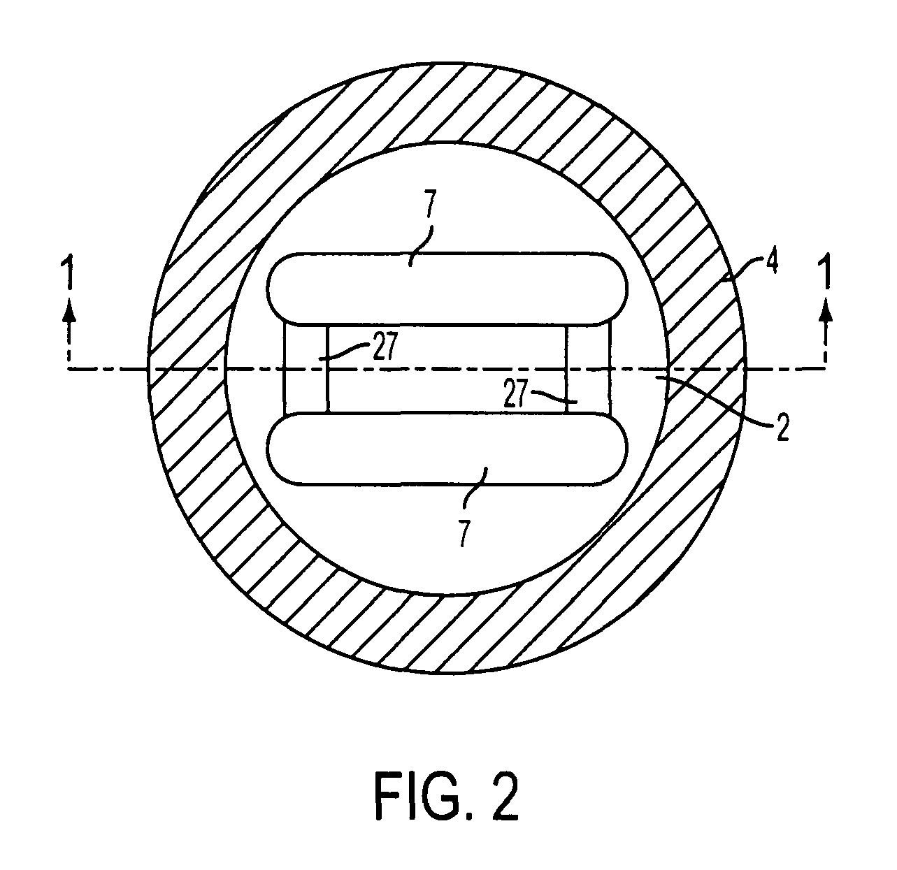
[0007]The invention provides an optical cell that is spectroscopically stable, and can be used for spectroscopic measurement in transmission, sample reflection, back plate reflection, emission, or scattering modes. The inventive cell allows fluid in a sample space to be exchanged without separating a front or a back plate from a spacer, allows a solid sample to be placed in or removed from the sample space, requires only a small amount of sample, and allows for different sample gaps to be easily and inexpensively set. The inventive cell and methods allow spectral measurements to be taken over wavelengths ranging at least from the mid-infrared to the vacuum ultraviolet, provide a simple path for light traveling through a sample, and allow fast kinetic processes to be detected and monitored reproducibly and sensitively.

Problems solved by technology

Prior optical cells do not mitigate effects of linear expansion of their components, such as U.K. Published Patent Application Number 2,071,355.
Some prior optical cells have other problems, such as U.S. Pat. No. 6,490,034 to Woias and Hillerich, in which the optical path length within the cell is not adjustable.
Prior optical cells also do not permit ready sample placement and change of fluids in the sample space.
Investigation of solid samples with an irregular surface with ATR can be difficult or impossible.

Method used


Image

  • Flow-through, inlet-gas-temperature-controlled, solvent-resistant, thermal-expansion compensated cell for light spectroscopy
  • Flow-through, inlet-gas-temperature-controlled, solvent-resistant, thermal-expansion compensated cell for light spectroscopy
  • Flow-through, inlet-gas-temperature-controlled, solvent-resistant, thermal-expansion compensated cell for light spectroscopy

Examples


Embodiment Construction

[0034]Embodiments of the invention are discussed in detail below. In describing embodiments, specific terminology is employed for the sake of clarity. However, the invention is not intended to be limited to the specific terminology so selected. A person skilled in the relevant art will recognize that other equivalent components can be employed and other methods developed without parting from the spirit and scope of the invention. All references cited herein are incorporated by reference as if each had been individually incorporated.

[0035]Optical cells for holding samples, controlling conditions such as bath fluid and temperature around a sample, and having excellent spectroscopic stability are required for a wide variety of experimental and analytical techniques. The invention provides spectroscopically stable optical cells for holding samples and controlling conditions such as bath fluid and temperature around a sample, for a wide variety of experimental and analytical techniques. ...


PUM

PropertyMeasurementUnit
temperatureaaaaaaaaaa
volumeaaaaaaaaaa
volumeaaaaaaaaaa

Abstract

Optical cells include a spacer formed of a hydrocarbon-resistant polymer, so that fluids such as hydrocarbons and alcohols can be introduced to a sample space, or include a fluid inlet and a heated inlet tube, so that a humid gas can be introduced to the sample space without condensation occurring. Optical cells can be used with, for example, solid, gel, and liquid samples. Measurements can be performed with various selected sample gaps of an optical cell.

Description

BACKGROUND OF THE INVENTION[0001]1. Field of the Invention[0002]The present invention relates to an optical cell. More particularly, the invention provides a flow-through optical cell in which changes in the dimension of component materials induced by changes in temperature are non-actively compensated to ensure that a sample gap of the sample space remains nearly constant, permitting reproducible spectroscopy despite variations in temperature.[0003]2. Description of the Related Art[0004]Prior optical cells do not mitigate effects of linear expansion of their components, such as U.K. Published Patent Application Number 2,071,355. Some prior optical cells have other problems, such as U.S. Pat. No. 6,490,034 to Woias and Hillerich, in which the optical path length within the cell is not adjustable.[0005]Prior optical cells also do not permit ready sample placement and change of fluids in the sample space. See “Quantitative Measurement of the IR Spectra of Water Solutions” by N. N. Kal...

Claims


Application Information

Patent Timeline
Patent Type & Authority Patents(United States)
IPC IPC(8): G01N33/20
CPCG01N21/0332G01N21/05G01N2021/0346
Inventor MERTZ, EDWARD L.SULLIVAN, JAMES V.
Owner GOVERNMENT THE
Why Eureka
Eureka Blog
Learn More