Purging apparatus and purging method

a technology of purging apparatus and purging method, which is applied in the direction of lighting and heating apparatus, application, packaging goods type, etc., can solve the problems of high cost to obtain the high clean environment, difficult to pass a gas having a sufficient flow rate through the upper and lower faces, and difficult to sufficiently remove contaminant or the like by a conventional method, etc., to achieve effective and secure removal of contaminant, and inexpensive and easy setting

Inactive Publication Date: 2006-12-07
TDK CORPARATION
View PDF22 Cites 44 Cited by
  • Summary
  • Abstract
  • Description
  • Claims
  • Application Information

AI Technical Summary

Benefits of technology

[0018] The present invention is made in view of the above situation and its object is to provide a purging method and a purging apparatus for a FOUP capable of effectively removing a contaminant or the like attached on a wafer.
[0031] According to the present invention, it is possible that a gas supply nozzle enters a pod from a pod opening to spray high clean gas on the surface of a wafer. Moreover, the gas supply nozzle can move in a direction in which wafers are superimposed and individually spray gas on each wafer. Therefore, it is possible to effectively and securely remove contaminant such as dust or impurity attached to the surface of a wafer. Moreover, it is possible to perform the operation for purging the inside of the pod any time during wafer treatment by using the gas supply nozzle and hold a wafer under a cleaner environment. Furthermore, the present invention can be executed for a mapping apparatus of an existing FOUP system by only adding a gas supply nozzle and a gas pipe, and can be set to a standardized system easily and inexpensively.
[0032] Furthermore, according to the present invention, a gas supply nozzle can spray high clean gas on the whole area of the surface of a wafer by keeping a predetermined distance from the wafer. Furthermore, the gas supply nozzle can move in a direction in which wafers are superimposed and it is possible to individually spray each wafer with gas. Therefore, it is possible to effectively and securely remove contaminant such as dust or impurity attached to the surface of a wafer. Moreover, it is possible to perform the operation for purging the inside of a pod any time during wafer treatment by using a gas supply nozzle and hold a wafer under a cleaner environment. Furthermore, it is possible to execute the present invention for the door of a load port of an existing FOUR system by only adding a gas supply nozzle and a gas pipe and inexpensively and easily set the present invention to a standardized system.

Problems solved by technology

However, because the diameter of a wafer is increased, the above method becomes a problem in cost to obtain the high clean environment.
Therefore, it is considered that it is difficult to pass a gas having a sufficient flow rate through the upper and lower faces of individual wafers held by keeping very small intervals.
However, contaminant or the like is mainly attached to the upper face or lower face of a wafer and therefore, it is considered that it is difficult to sufficiently remove contaminant or the like by a conventional method.
However, it is considered that it is also difficult to effectively replace the gas present between wafers held by keeping very small spaces.
Therefore, it is considered that it is also difficult to obtain an effect for removing contaminant attached to the upper and lower faces of a wafer.
However, it is considered that it is difficult to keep the inside diameter of a gas introducing channel at a large value from the viewpoint of an actual configuration.
Therefore, the pod disclosed in Japanese Patent Application Laid-Open No. 11-251422 requiring a configuration different from the standard has a problem that the pod cannot be shared with a support pedestal generally used at present.

Method used


Image

  • Purging apparatus and purging method
  • Purging apparatus and purging method
  • Purging apparatus and purging method

Examples


first embodiment

[0058] First embodiment of the present invention is described below by referring to the accompanying drawings.

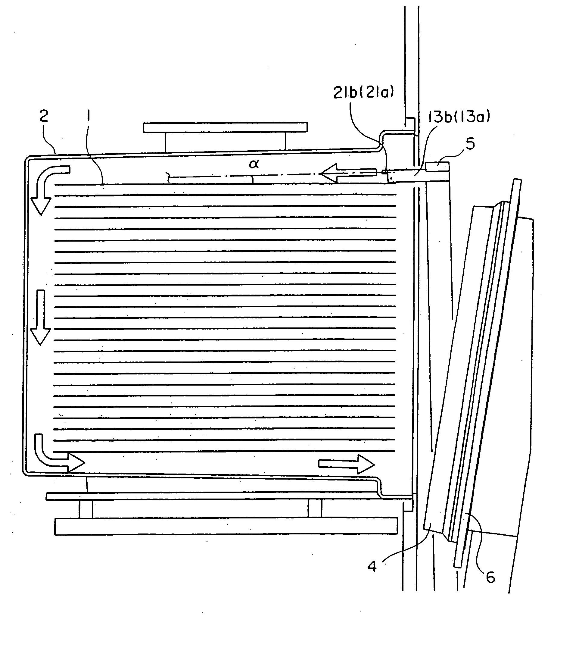
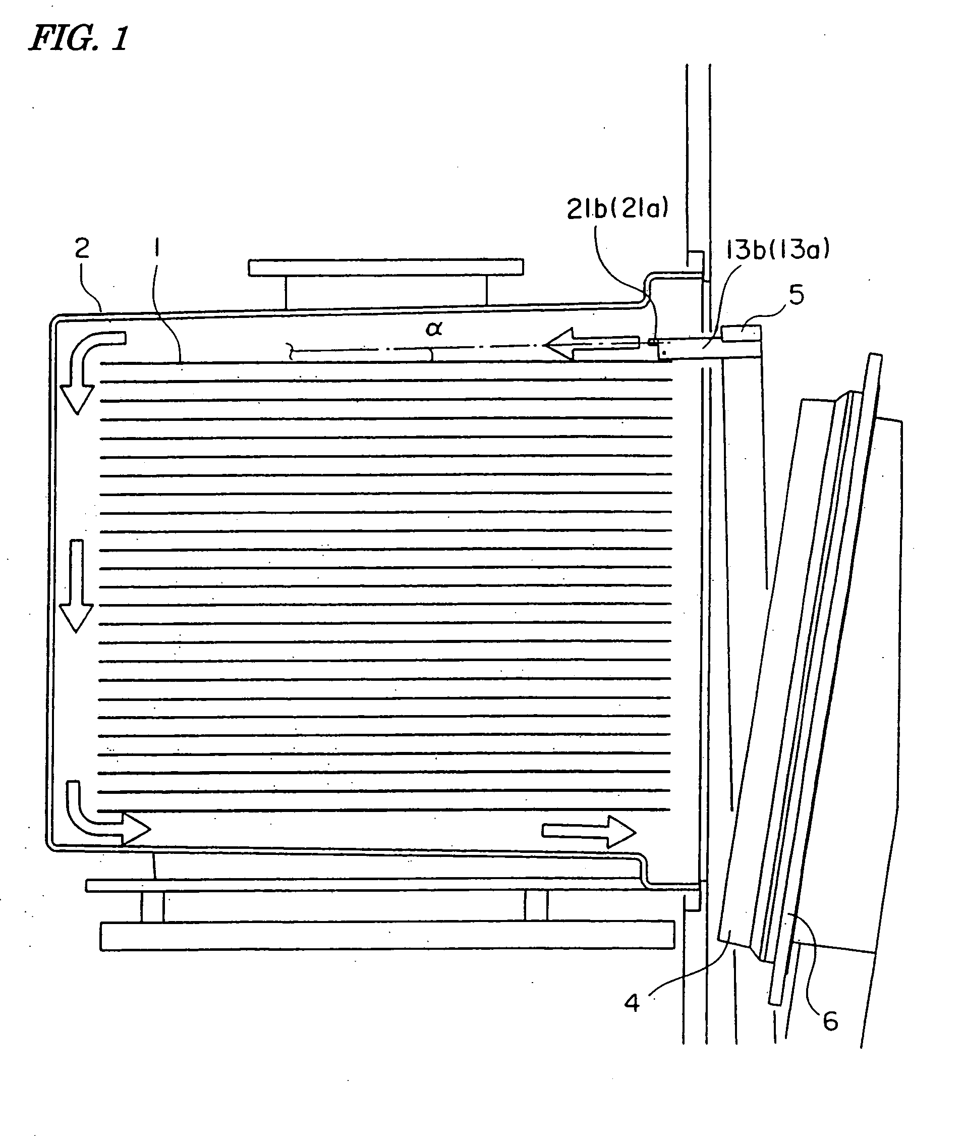
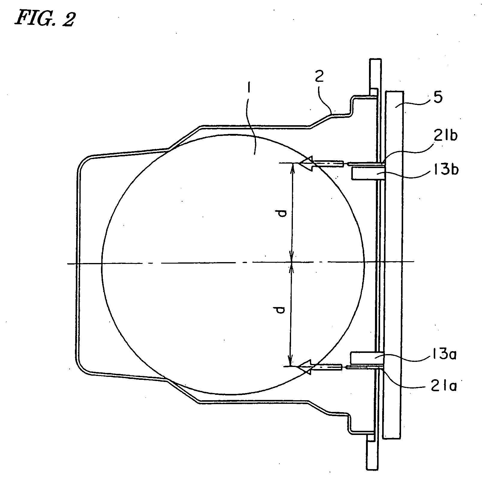
[0059]FIG. 1 shows a schematic configuration of a purging apparatus of the present invention, which is an illustration showing the outline when viewing a pod, a wafer housed in the pod, and a purging apparatus of the present invention from a side. FIG. 2 is an illustration showing the outline of an essential portion when viewing each configuration shown in FIG. 1 and configurations following each configuration from above. Various configurations such as a shelf for supporting a wafer and sealing member set between a lid and a pod and the like are originally included in the pod and various configurations follow a door. However, because these configurations are not directly related to the present invention, detailed illustration and description are omitted.

[0060] In FIG. 1, a frame 5 constituted of a frame member is set so as to surround the circumference of a door 6 of an op...

second embodiment

[0093] Second embodiment of the present invention is described below by referring to the accompanying drawings. FIGS. 8A to 8C are illustrations relating to a schematic configuration of a purging apparatus of the present invention, which are illustrations showing the outline of a state when viewing a pod, a wafer housing in the pod, and the purging apparatus of the present invention from a side. FIG. 8A shows the time of starting the purging operation, FIG. 8B shows the middle of the purging operation, and FIG. 8C shows an enlarged view of an essential portion of the purging apparatus. Moreover, FIG. 9A is an illustration showing an essential portion when viewing the configurations shown in FIGS. 8A to 8C and a configuration following the configurations from their upper potion and FIG. 9B is an illustration when cutting an essential portion of the purging apparatus by a horizontal face and viewing the essential portion from the upper portion. A shelf for supporting a wafer, sealing ...


PUM

PropertyMeasurementUnit
diameteraaaaaaaaaa
angleaaaaaaaaaa
areaaaaaaaaaaa

Abstract

It is an object of the present invention to easily and securely perform the removal operation of contaminant or the like from a wafer housed in a FOUP. To achieve the object, a purging apparatus of the present invention removes contaminant or the like from a wafer by moving a gas supply nozzle along a direction in which wafers are superimposed at the front of an opening while a lid of the FOUP is separated from a body and spraying clean gas on each wafer from the gas supply nozzle.

Description

TECHNICAL FIELD [0001] The present invention relates to a product housing container used to house a product in a product manufacturing process in which the process of a semiconductor, panel for a flat panel display, optical disk, or the like is performed in a high clean environment. More minutely, the present invention relates to a cleaning method of the inside of the so-called FOUP (front-opening unified pod) used in a process for treating a semiconductor wafer mainly having a diameter of 300 mm as a product to be housed. BACKGROUND ART [0002] A process for fabricating a semiconductor device has dealed with high cleaning so far in a requested process by forming the whole plant for applying various treatments to a wafer into a clean room. However, because the diameter of a wafer is increased, the above method becomes a problem in cost to obtain the high clean environment. Means for securing a mini-environment (very small environment) space keeping a high cleaning degree has been tak...

Claims


Application Information

Patent Timeline
Patent Type & Authority Applications(United States)
IPC IPC(8): F26B19/00H01L21/00H01L21/67H01L21/677H01L21/673H01L21/68
CPCH01L21/67017H01L21/67772H01L21/67389Y10S414/135
Inventor MIYAJIMA, TOSHIHIKO
Owner TDK CORPARATION
Why Eureka
Try Eureka