
Apparatus and method for encoding motion vector, and program and medium therefor

a motion vector and motion vector technology, applied in the field of apparatus and method for encoding motion vector, can solve the problems of increasing unable to determine a scale factor, and the inability to reduce the f_code, so as to reduce the mv code length

Inactive Publication Date: 2011-03-01
GK BRIDGE 1
View PDF6 Cites 7 Cited by
  • Summary
  • Abstract
  • Description
  • Claims
  • Application Information

AI Technical Summary

Benefits of technology

The present invention provides a motion vector encoding method that can reduce the length of MV codes by utilizing past MV information. The method includes detecting motion vectors of a to-be-encoded picture and a reference picture, generating motion vector predictors from the motion vectors, calculating the average value of differential vectors between the motion vectors and the motion vector predictors, determining a parameter representing a motion vector encodable range based on the average value of the differential vectors, and encoding the motion vectors based on the differential vectors and the parameter. The invention also provides a motion vector decoding apparatus and a motion vector encoding apparatus. The technical effect of the invention is to improve the efficiency and accuracy of motion vector encoding and decoding.

Problems solved by technology

Depending on scenes, however, there occurs a problem that the MV predictor considerably differs from the MV, which results in an increase of the MV code length.
In the above methods, however, it is impossible to determine a scale factor until all of the MVs of the picture are detected.
That is, the above-described conventional methods have a problem in that, in encoding a certain picture, an f_code cannot be determined to reduce an MV code length unless all the MVs of the picture are calculated.

Method used


Image

  • Apparatus and method for encoding motion vector, and program and medium therefor
  • Apparatus and method for encoding motion vector, and program and medium therefor
  • Apparatus and method for encoding motion vector, and program and medium therefor

Examples


first preferred embodiment

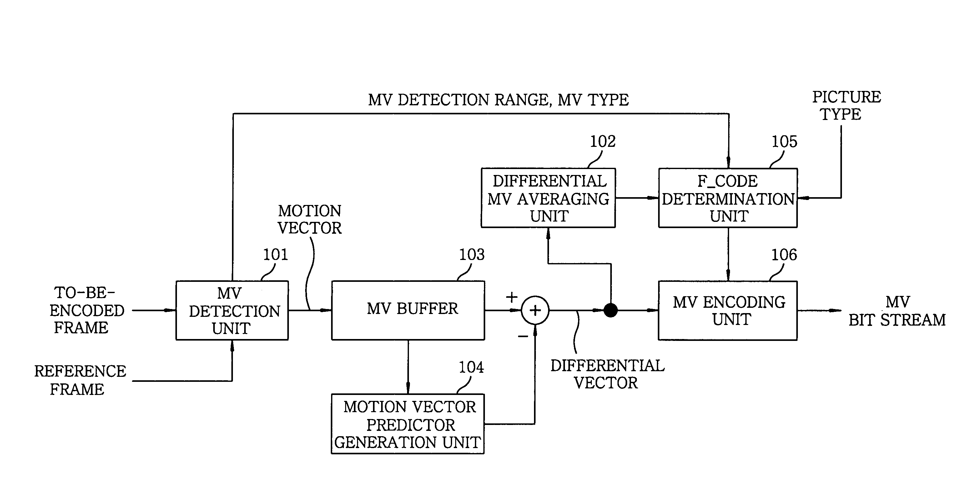
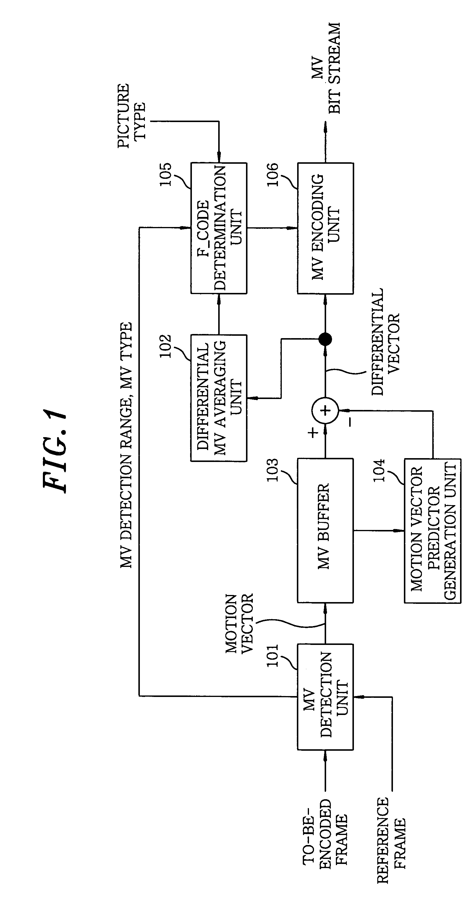
[0021]With reference to FIG. 1, there is illustrated a configuration of an MPEG-based MV encoding apparatus in accordance with a first preferred embodiment of the present invention. Reference numeral 101 is an MV detection unit which receives a to-be-encoded frame and a reference frame inputted thereto, detects an MV within a predetermined vector search range (f_code) for every MB, and then outputs the detected MVs, the MV detection range and an MV type that indicates a forward vector type or a backward vector type. Reference numeral 103 represents an MV buffer for temporarily storing the MVs therein, and reference numeral 104 denotes an MV predictor generation unit for generating MV predictors from the MVs stored in MV buffer 103. Reference numeral 102 refers to a differential MV averaging unit that summates differential vectors for 1 frame, which represents differences between the respective MVs outputted from MV buffer 103 and the MV predictors outputted from MV predictor generat...

second preferred embodiment

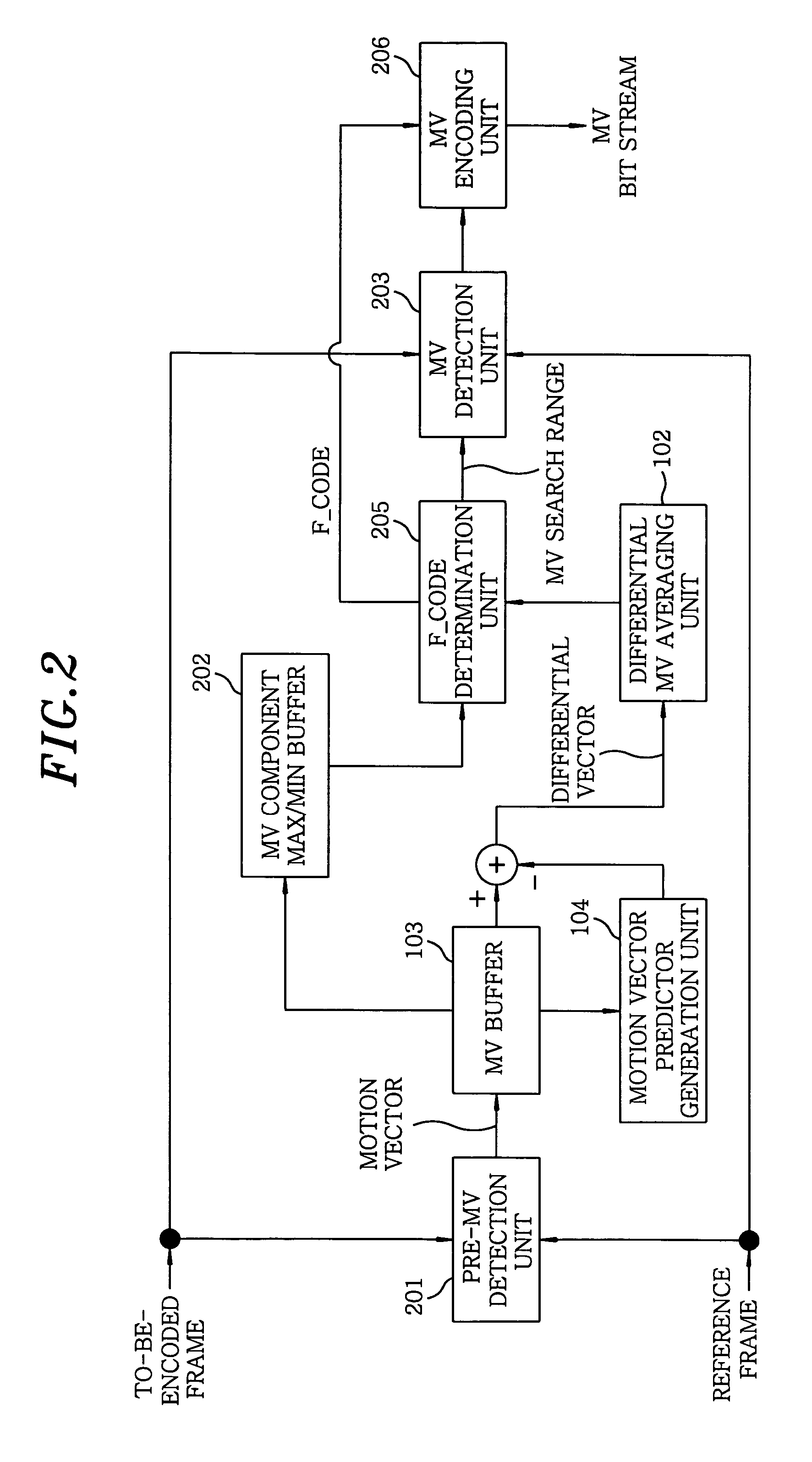
[0024]FIG. 2 illustrates a configuration of an MPEG-based MV encoding apparatus in accordance with a second preferred embodiment of the present invention. In FIG. 2, parts identical to those described in the first preferred embodiment will be assigned like reference numerals, and description thereof will be omitted. The difference between the first and the second preferred embodiments lies in that, in accordance with the second preferred embodiment, it is possible to obtain an f_code by utilizing detected MVs, thereby avoiding a delay caused by using the past f_code.

[0025]Reference numeral 201 is a pre-MV detection unit that is employed to determine an f_code by detecting MVs, that is, without deciding an MV search range from the past information. Pre-MV detector 201 receives a to-be-encoded frame and a reference frame inputted thereto, detects MVs of some MBs prior to the encoding, and outputs the detected MVs. Reference numeral 202 is a buffer for storing maximum and minimum value...

third preferred embodiment

[0028]FIG. 3 illustrates a configuration of an MPEG-based MV encoding apparatus in accordance with a third preferred embodiment of the present invention. In FIG. 3, parts identical to those described in the first or the second preferred embodiment will be assigned like reference numerals, while omitting description thereof. Reference numeral 301 is a stream buffer of, e.g., a frame and reference numeral 302 represents an MV decoding unit that receives a stream from stream buffer 301 and decodes MVs thereof. Reference numeral 206 is an MV encoding unit for encoding the MVs of MV buffer 103 with an f_code determined by f_code determination unit 205. Further, reference numeral 303 represents a MV combining unit for substituting the encoded MVs outputted from the MV encoding unit 206 for the MVs of the stream.

[0029]In accordance with the third preferred embodiment, with regard to a previously encoded stream, MVs of the encoded stream are re-encoded with a newly determined f_code. With t...


PUM


Abstract

A motion vector encoding apparatus includes a detection unit for detecting motion vectors of respective blocks of a predetermined size and a range of the motion vectors; a first storage unit for storing therein the detected motion vectors; and a generation unit for generating motion vector predictors from the motion vectors outputted from the first storage unit. The apparatus also includes a calculation unit for calculating an average value of differential vectors between the motion vectors outputted from the first storage unit and the motion vector predictors. Moreover, the apparatus includes a determination unit for determining a parameter representing a motion vector encodable range based on the average value of the differential vectors calculated by the calculation unit; and an encoding unit for encoding the motion vectors based on the differential vectors and a parameter representing an encodable range outputted from the determination unit.

Description

FIELD OF THE INVENTION[0001]The present invention relates to an apparatus and a method for encoding a motion vector (hereinafter, simply referred to as an MV) during video compression encoding.BACKGROUND OF THE INVENTION[0002]With regard to video compression encoding, encoding of an MV is generally carried out by encoding a difference between the MV and an MV predictor, thereby reducing a code length assuming that the MV predictor is almost exact. Depending on scenes, however, there occurs a problem that the MV predictor considerably differs from the MV, which results in an increase of the MV code length. In an MPEG (moving picture expert group), encoding of the MV involves calculating a differential vector between the MV and the MV predictor that is determined in accordance with a certain method; and encoding the differential vector. The differential vector can be expressed by scaling a basic differential vector using a scale factor and adding a residual vector to the scaled result...

Claims


Application Information

Patent Timeline
Patent Type & Authority Patents(United States)
IPC IPC(8): H04N7/12H04N11/02H04N11/04H04B1/66H04N5/14H04N7/26H04N7/32
CPCH04N19/52H04N5/145H04N19/51
Inventor KAWAHARADA, MAKOTO
Owner GK BRIDGE 1
Learn More