Lossless compression-encoding device

a lossless compression and encoder technology, applied in the field of lossless compression encoders, can solve the problems of inability to achieve sufficient compression effects, large amount of data of finally obtained variable-length codes, and lossless compression algorithms that cannot obtain sufficient prediction accuracy, etc., to achieve the effect of reducing the code length of variable-length codes

Active Publication Date: 2012-11-13
YAMAHA CORP
View PDF8 Cites 2 Cited by
  • Summary
  • Abstract
  • Description
  • Claims
  • Application Information

AI Technical Summary

Benefits of technology

[0007]The invention has been made in view of the above circumstances and it is an object of the invention to improve the compression ratio when the dynamic range of data that is to be compressed is large in a lossless compression-encoding device that uses both differential coding and variable-length coding.
[0009]According to the invention, the prediction error conversion part performs reversal of the sign bit of the prediction error obtained through differential coding when reversal of the sign bit of the prediction error decreases the absolute value of the prediction error, and the variable-length coding part performs variable-length coding, that decreases a code length as an absolute value of the prediction error decreases, on the prediction error that has been processed by the prediction error conversion part to generate a variable-length code representing the prediction error. Therefore, the absolute value of a prediction error that is to be subjected to variable-length code is reduced on the whole so that it is possible to reduce the code length of the variable-length code as a whole.

Problems solved by technology

This type of lossless compression algorithm cannot obtain sufficient prediction accuracy when the correlation between adjacent pixels of an image is weak.
Therefore, the absolute value of a prediction error obtained through differential coding is generally large so that the total amount of data of a finally obtained variable-length code is large.
Thus, it is not possible to achieve sufficient compression effects.

Method used


Image

  • Lossless compression-encoding device
  • Lossless compression-encoding device
  • Lossless compression-encoding device

Examples


Embodiment Construction

[0021]The embodiments of the invention will now be described with reference to the drawings.

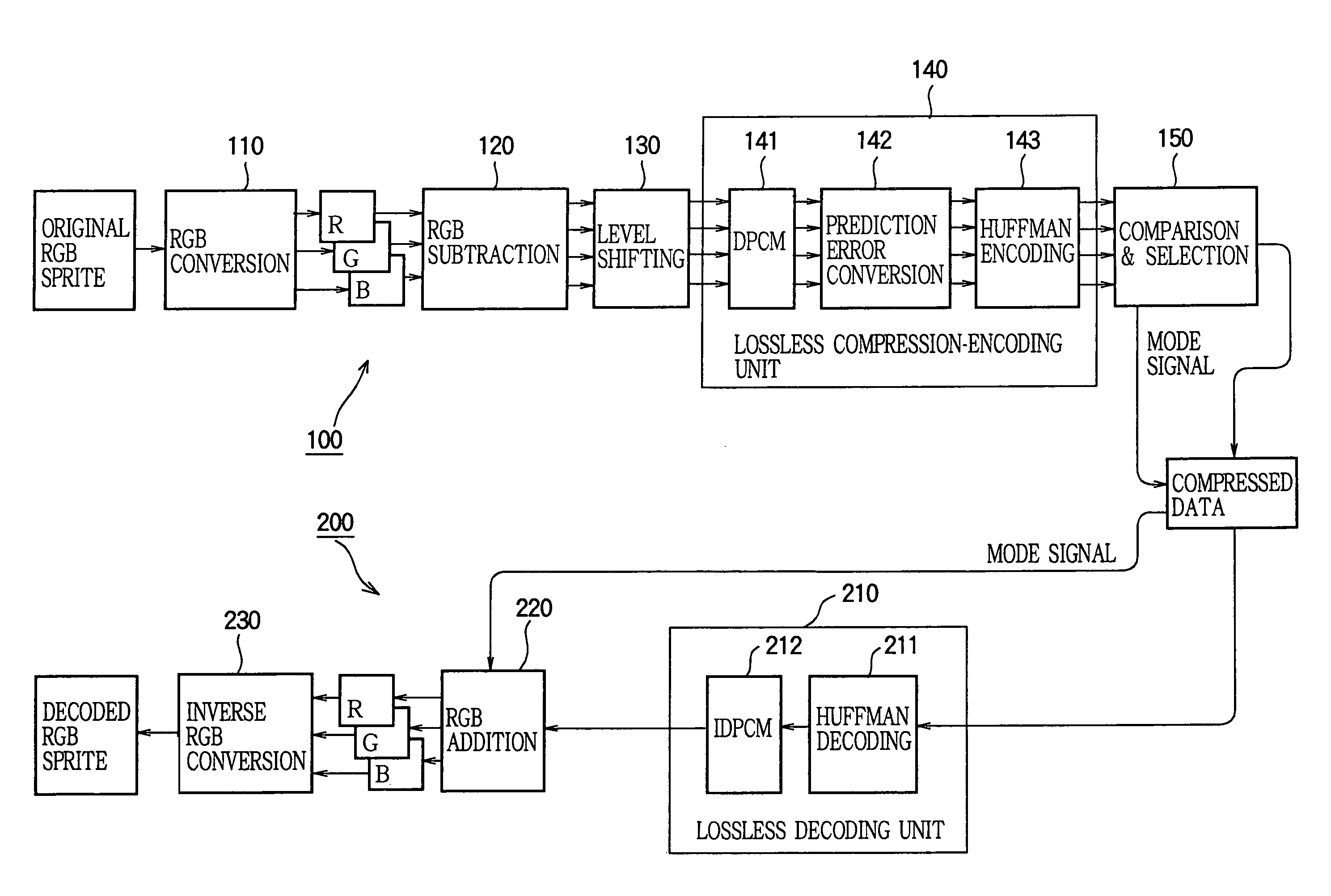
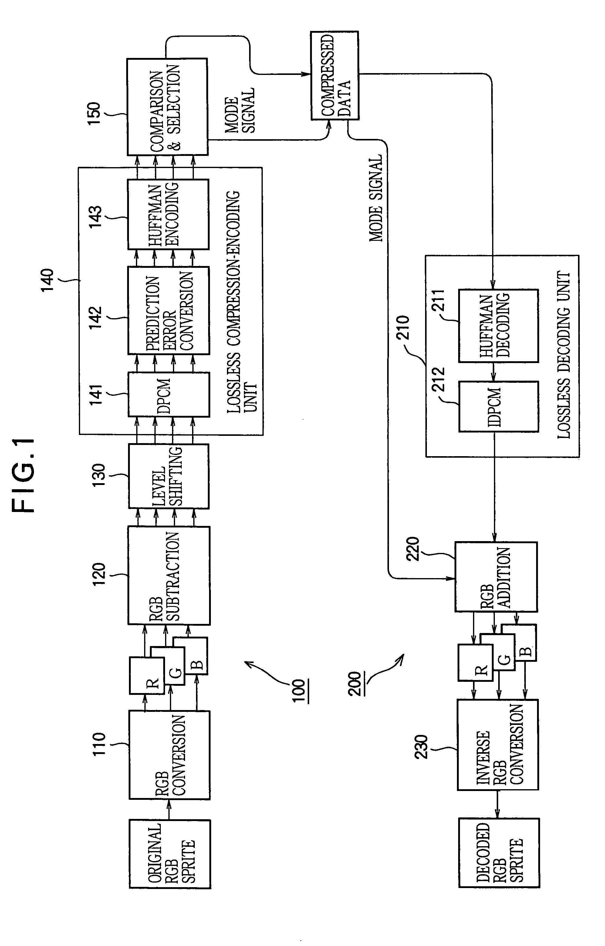
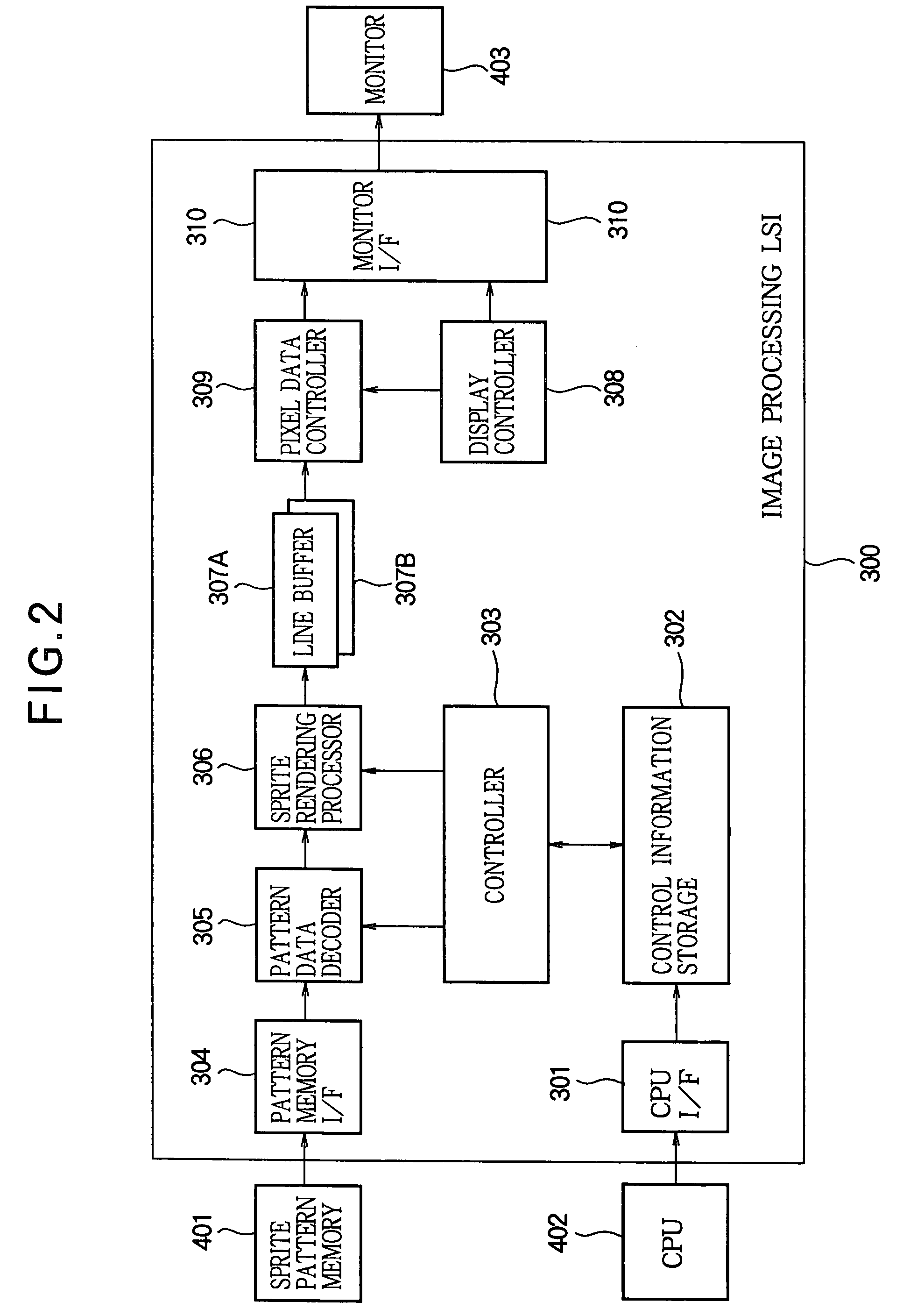
[0022]FIG. 1 is a block diagram illustrating a configuration of a system that includes an encoding device 100 and a decoding device 200 according to an embodiment of the invention and that performs reversibly compressed transmission of a sprite image. FIG. 2 is a block diagram illustrating a configuration of an image processing LSI 300 that decodes compressed data of an image output by the encoding device 100 and that reproduces the compressed data as the image. Of the components of the image processing LSI 300, only those associated with decoding and reproduction of compressed data are illustrated in FIG. 2 and other components are not illustrated.

[0023]First, a description is given of the image processing LSI 300 with reference to FIG. 2, before the encoding device 100 and the decoding device 200 are described. In FIG. 2, a sprite pattern memory 401 stores compressed data of a plurality of ...


PUM


Abstract

In a lossless compression-encoding device, a differential coding part calculates a prediction value of data to be compressed, and calculates a prediction error that is a difference between the prediction value and an actual value of the data to be compressed. A prediction error conversion part performs reversal of a sign bit of the prediction error output by the differential coding part in case that the reversal of the sign bit of the prediction error decreases an absolute value of the prediction error. A variable-length coding part performs variable-length coding on the prediction error that has been processed by the prediction error conversion part to generate a variable-length code representing the prediction error, and outputs the variable-length code as compressed data in such a manner that a code length of the compressed data decreases as the absolute value of the prediction error decreases.

Description

BACKGROUND OF THE INVENTION[0001]1. Technical Field of the Invention[0002]The present invention relates to a lossless compression-encoding device for data such as image data or audio data.[0003]2. Description of the Related Art[0004]Image data compression technologies can be mainly classified into lossy compression technologies and lossless compression technologies. Lossy compression technologies mostly use orthogonal transformation and have an advantage in that they obtain a high compression ratio although it is not possible to completely reconstruct original image data from compressed data.[0005]On the other hand, lossless compression technologies have an advantage in that it is possible to completely reconstruct original image data from compressed data although a high compression ratio is not obtained. Therefore, lossless compression technologies are used for purposes such as storage or exchange of medical images. One lossless compression technology is described in Japanese Paten...

Claims


Application Information

Patent Timeline
Patent Type & Authority Patents(United States)
IPC IPC(8): G06K9/36G06K9/46H03M7/36H04N1/41H04N11/04H04N19/136H04N19/146H04N19/182H04N19/186H04N19/50H04N19/593H04N19/90H04N19/91
CPCH04N19/46H04N19/593H04N19/184H04N19/186H04N19/182H04N19/91
Inventor NISHIKAWA, YUKINARIHONME, MITSUHIRO
Owner YAMAHA CORP
Why Eureka
Try Eureka