Laryngeal mask with esophageal blocker and bite block

Active Publication Date: 2011-03-08
SALTER LABS LLC
View PDF164 Cites 16 Cited by
  • Summary
  • Abstract
  • Description
  • Claims
  • Application Information

AI Technical Summary

Benefits of technology

There is also described herein, a laryngeal mask including a bite block, the mask comprising: a respiratory tube having a hollow passageway there through; a shield comprising an inflatable outer ring and a posterior base; and a bite block formed onto said respiratory tube; wherein said bite block

Problems solved by technology

Still further, it has been recognized that many patients who need a supraglottic airway have lost muscle control and can involuntarily bite down on

Method used


Image

  • Laryngeal mask with esophageal blocker and bite block
  • Laryngeal mask with esophageal blocker and bite block
  • Laryngeal mask with esophageal blocker and bite block

Examples


Embodiment Construction

)

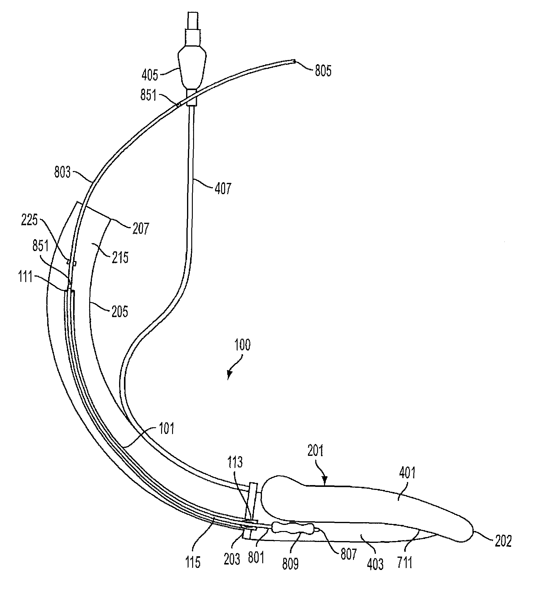
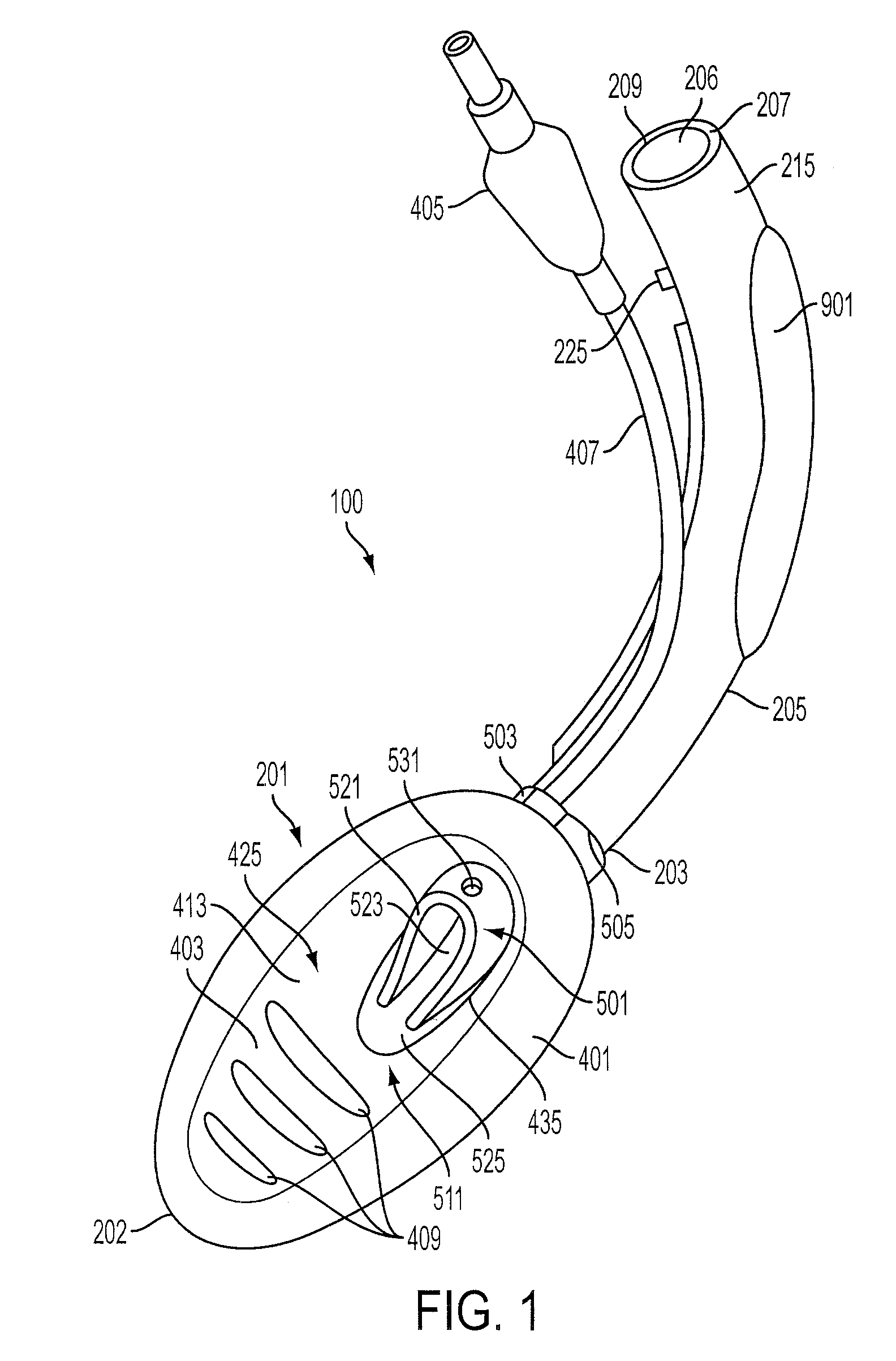
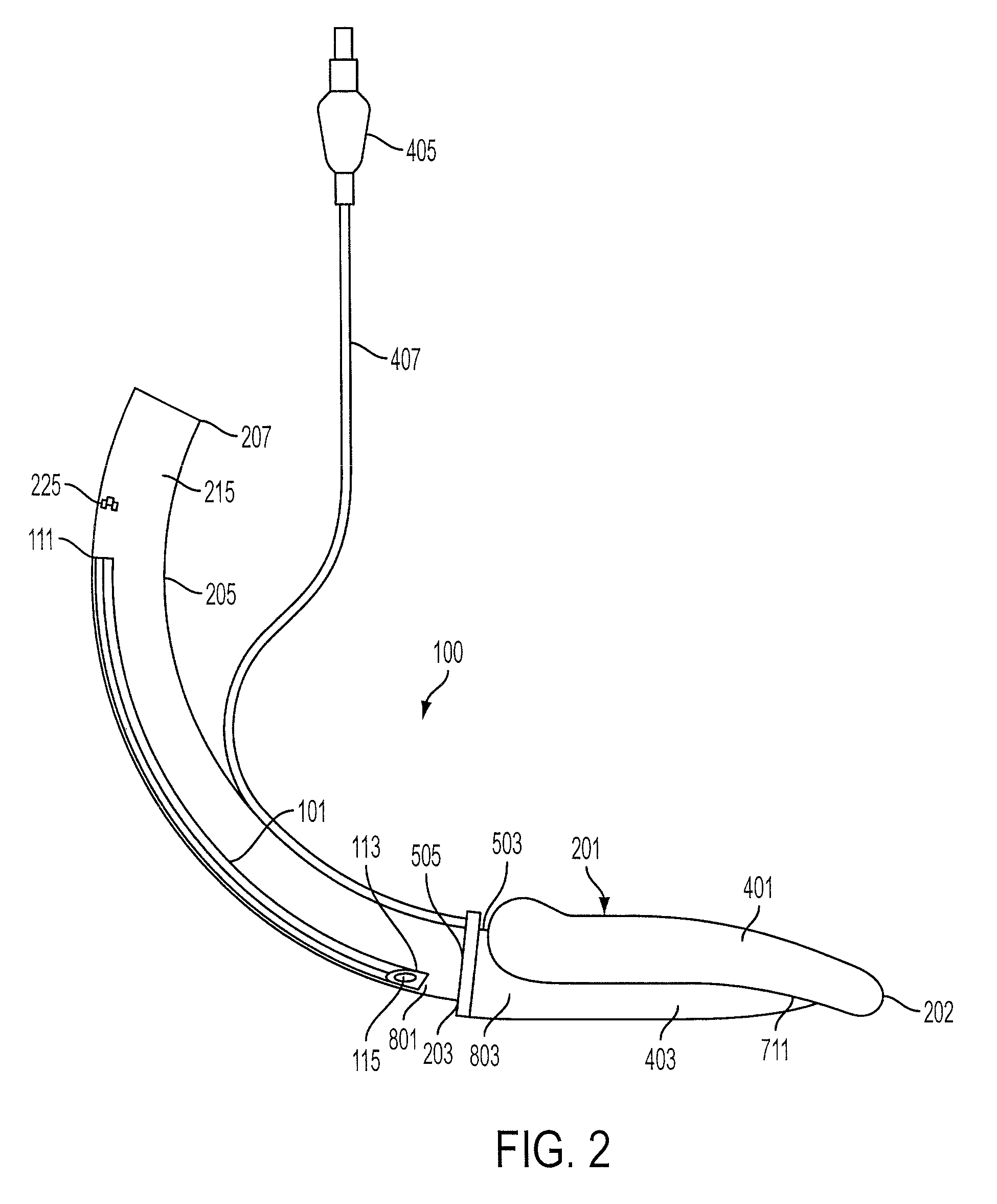
The following detailed description illustrates by way of example and not by way of limitation. Described herein, among other things, is an embodiment of a supraglottic airway which is designed for use with an esophageal blocker. Specifically, the supraglottic airway includes structures which enable the airway to transport an esophageal blocker into the oropharynx area when the airway is inserted, and then facilitate the deployment of the esophageal blocker into the esophagus either during placement or once the airway is positioned. While the supraglottic airway described herein incorporates certain features for improved placement in the airway, it should be recognized that these features are not required for use of the esophageal blocker and the esophageal blocker and associated components attached to the airway can be used on any form of supraglottic airway.

FIGS. 1-6 provide for an embodiment of a supraglottic airway in the form of removable laryngeal mask airway (100). The mask (...


PUM


Abstract

A supraglottic airway of the type used to facilitate lung ventilation and the insertion of endo-tracheal tubes or related medical instruments through a patient's laryngeal opening including a guide structure for use in deploying an esophageal blocker into the patient's esophagus and additionally or alternatively including a bite block for inhibiting a patient from biting an internal passageway in the respiratory tube of the airway closed.

Description

BACKGROUND1. Field of the InventionThe invention relates to an artificial airway device more specifically to a supraglottic airway designed to guide an esophageal blocker device into the esophagus and including a bite block.2. Description of the Related ArtIn general, supraglottic airways such as laryngeal masks allowing for both rapid lung ventilation and the insertion of medical instruments and tubes into the laryngeal openings of patients have been described in patents, such as U.S. Pat. No. 4,509,514 to Brain and U.S. Pat. Nos. 6,422,239 and 5,937,860 to Cook the entire disclosures of which were herein incorporated by reference. Laryngeal masks generally consist of two major components, a breathing tube and an inflatable mask, these devices are inserted into a patient's throat, and when properly positioned, cover the laryngeal opening. A seal is then formed around the circumference of the laryngeal opening by the inflation of a ring-like structure located toward the front of the...

Claims


Application Information

Patent Timeline
IPC IPC(8): A61M16/04
CPCA61M16/04A61M16/0488A61M16/0409A61M16/0415A61M16/0493
Inventor COOK, DANIEL J.
Owner SALTER LABS LLC
Why Eureka
Try Eureka