Laryngoscope blade

a technology of laryngoscope and blade, which is applied in the field of laryngoscope blade, can solve the problems of affecting the endotracheal tube, affecting the further intubation of patients, and the device is extremely large, so as to improve the examination of intubated patients and simplify the examination process

Inactive Publication Date: 2007-06-07
ASHFAQUE MUHAMMAD
View PDF8 Cites 13 Cited by
  • Summary
  • Abstract
  • Description
  • Claims
  • Application Information

AI Technical Summary

Benefits of technology

[0009] The present invention seeks to overcome the prior art disadvantages and provide improved laryngoscope blades. In particular, the laryngoscope blades of the present invention are designed to overcome the problem of effecting access to the mouth, larynx and / or pharynx of an intubated patient, and allow for the simplification of examination of an intubated patient and of further intubating a patient.

Problems solved by technology

As can be seen from their figures, the devices are extremely large, providing no possibility of viewing the interior of the mouth etc. other than by use of the telescope incorporated therein, which is far from ideal—there is no opportunity to view areas beyond the limited field of view of the telescope.
In addition, the devices hinder the further intubation of patients, which can be necessary as discussed above.
Also, removal of the laryngoscope without affecting the endotracheal tube is not convenient, particularly due to the need to move the loop relative to the tube, which may frequently result in movement of the tube.
Existing laryngoscope blades are useful in effecting endotracheal intubation, but they are of limited use when a physician wishes to examine behind an already inserted endotracheal tube, for example to examine the hypopharynx.

Method used


Image

  • Laryngoscope blade
  • Laryngoscope blade
  • Laryngoscope blade

Examples


Embodiment Construction

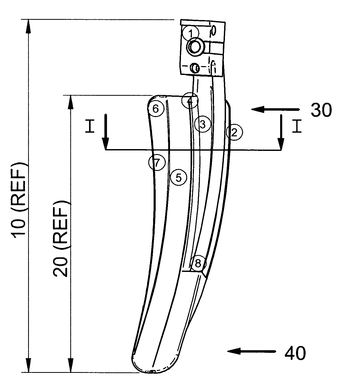
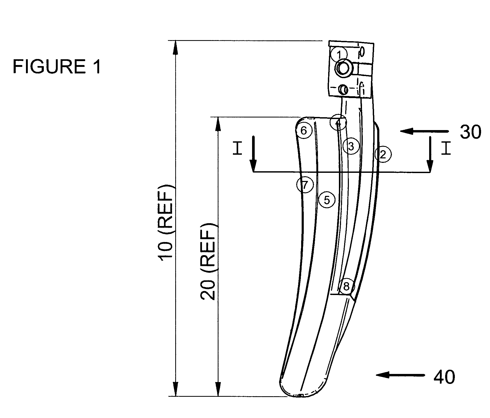
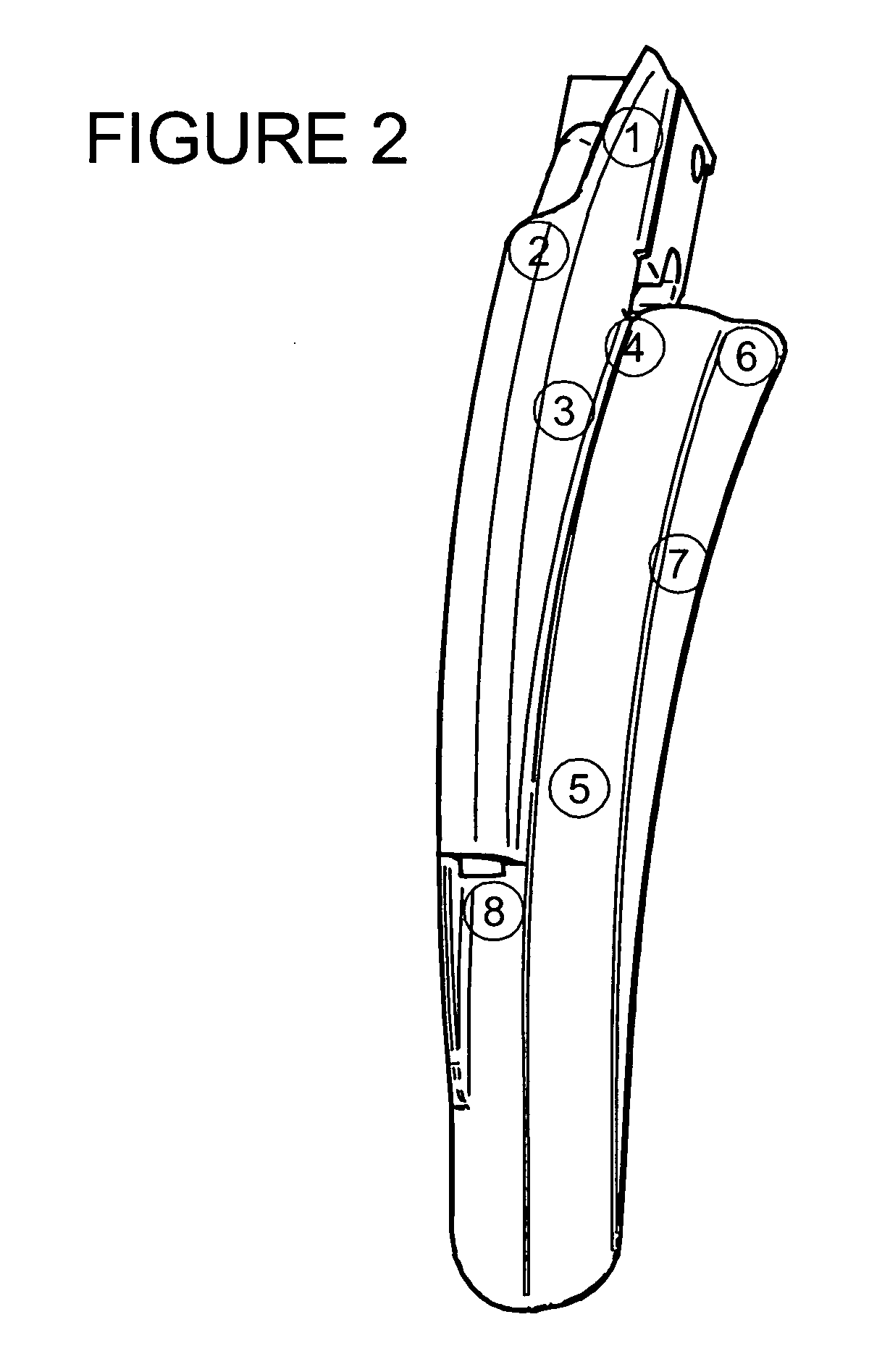
[0048] A specific example of a laryngoscope blade is shown in the accompanying Figures. As can be seen from FIG. 1, the laryngoscope blade 10 comprises a body 1 which is adapted for attachment to standard laryngoscope handles (not shown). When attached, the laryngoscope handles extend in FIG. 1 towards the viewer. Where the laryngoscope blade 10 requires a power source, for example for powering lighting means then that power may be supplied via the handle.

[0049] The blade 10 comprises an elongate arm 20 extending in a longitudinal direction, elongate arm 20 having a proximal end 30 adjacent body 1 and a distal end 40. Elongate arm 20 comprises a longitudinally elongate portion 5 (also referred to as a “furrow”) having a generally arcuate cross-section defining a convex upper surface (not shown in FIG. 1), a concave lower surface and first and second edges.

[0050] A first flange 6,7 is connected to the first edge of the arcuate cross-section 5 and defines a lateral edge of the arm. ...


PUM


Abstract

The present invention concerns improved laryngoscope blades, particularly for use in the intubation of patients, for example orotracheal and nasotracheal intubation, and which allow viewing of a portion of the mouth, the pharynx, and the larynx of a patient, and depress the tongue and the structures of the floor of the mouth in order to prevent the tongue of the patient from obstructing the view during examination.

Description

BACKGROUND OF THE INVENTION [0001] The present invention concerns improved laryngoscope blades, particularly for use in the intubation of patients, for example orotracheal and nasotracheal intubation, and which allow viewing of a portion of the mouth, the pharynx, and the larynx of a patient, and depress the tongue and the structures of the floor of the mouth in order to prevent the tongue of the patient from obstructing the view during examination. [0002] Generally, laryngoscopes have a blade mounted on a bracket and handle for manipulation by a physician. The blade has a lower (inner, lingual) surface for engaging and compressing the tongue of a patient onto the floor of the mouth of the patient, and an upper (outer, dorsal) surface over which the physician obtains a direct line of sight through the mouth to the opening through the larynx to the trachea. A large number of laryngoscope blades are known and generally have the IPC Classification code A61B 1 / 267. Examples include WO 0...

Claims


Application Information

Patent Timeline
Patent Type & Authority Applications(United States)
IPC IPC(8): A61B1/267
CPCA61B1/267
Inventor ASHFAQUE, MUHAMMAD
Owner ASHFAQUE MUHAMMAD
Why Eureka
Try Eureka