
Laryngeal mask airway device

a technology of airway device and laryngeal mask, which is applied in the direction of breathing mask, breathing protection, other medical devices, etc., can solve the problems of substantially self-inserting of the lma device when properly deflated, and achieve the effect of reducing the likelihood of any hard or angular edges, reducing the likelihood of any prontory edge, and being convenient to defla

Inactive Publication Date: 2006-11-16
TELEFLEX LIFE SCI PTE LTD
View PDF99 Cites 17 Cited by
  • Summary
  • Abstract
  • Description
  • Claims
  • Application Information

AI Technical Summary

Benefits of technology

[0005] The present invention seeks to eliminate the disadvantages associated with such undesirable insertion by minimizing the risk of the deflated cuff formation becoming folding over on itself during the insertion procedure. This is achieved by incorporating into the cuff at its distal end a reinforcing rib which serves to stiffen the leading end of the LMA-device during the course of the procedure for its insertion.
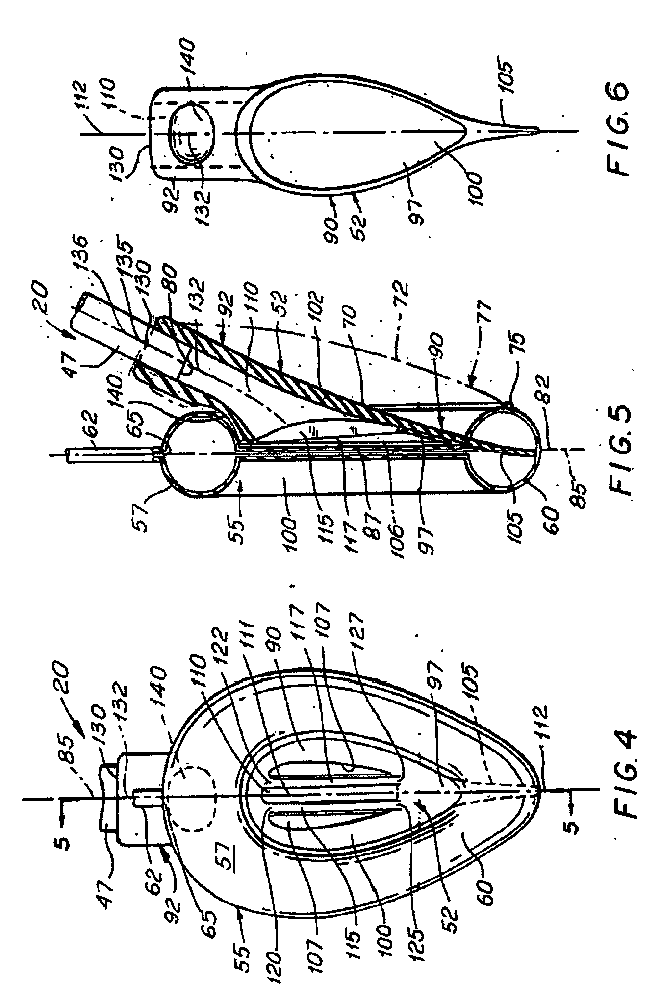
[0008] The LMA-device of the invention incorporating such a reinforcing rib has a number of advantages over and above that for which it was specifically devised. Thus, not only does the reinforcing rib largely eliminate the likelihood of the distal end of the deflated cuff formation folding over on itself during insertion of the LMA-device into the patient's throat, but also the cuff is easier to deflate preferably since the reinforcing rib will urge the deflating cuff into the desired orientation. Since the cuff in its deflated state may adopt an upturned or down turned orientation, the reinforcing rib will urge the deflated cuff into the down turned position desirable for insertion into the patient. Further, in addition to the rib being stiffer than the deflated cuff, it will preferably also be more compliant than the material of the bowl of the mask and the stiffness gradient formed by the rib and the mask will assist in the insertion of the device and substantially reduce the likelihood of any hard or angular edges of the bowl of the mask being presented which may subject the patient's throat to undesirable forces. Additionally, the rib will substantially reduce the promontory previously formed by the distal end of the mask structure, rendering the LMA-device substantially self-inserting when it is properly deflated.
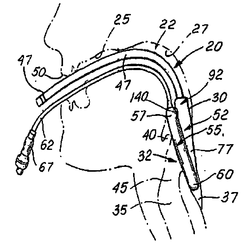
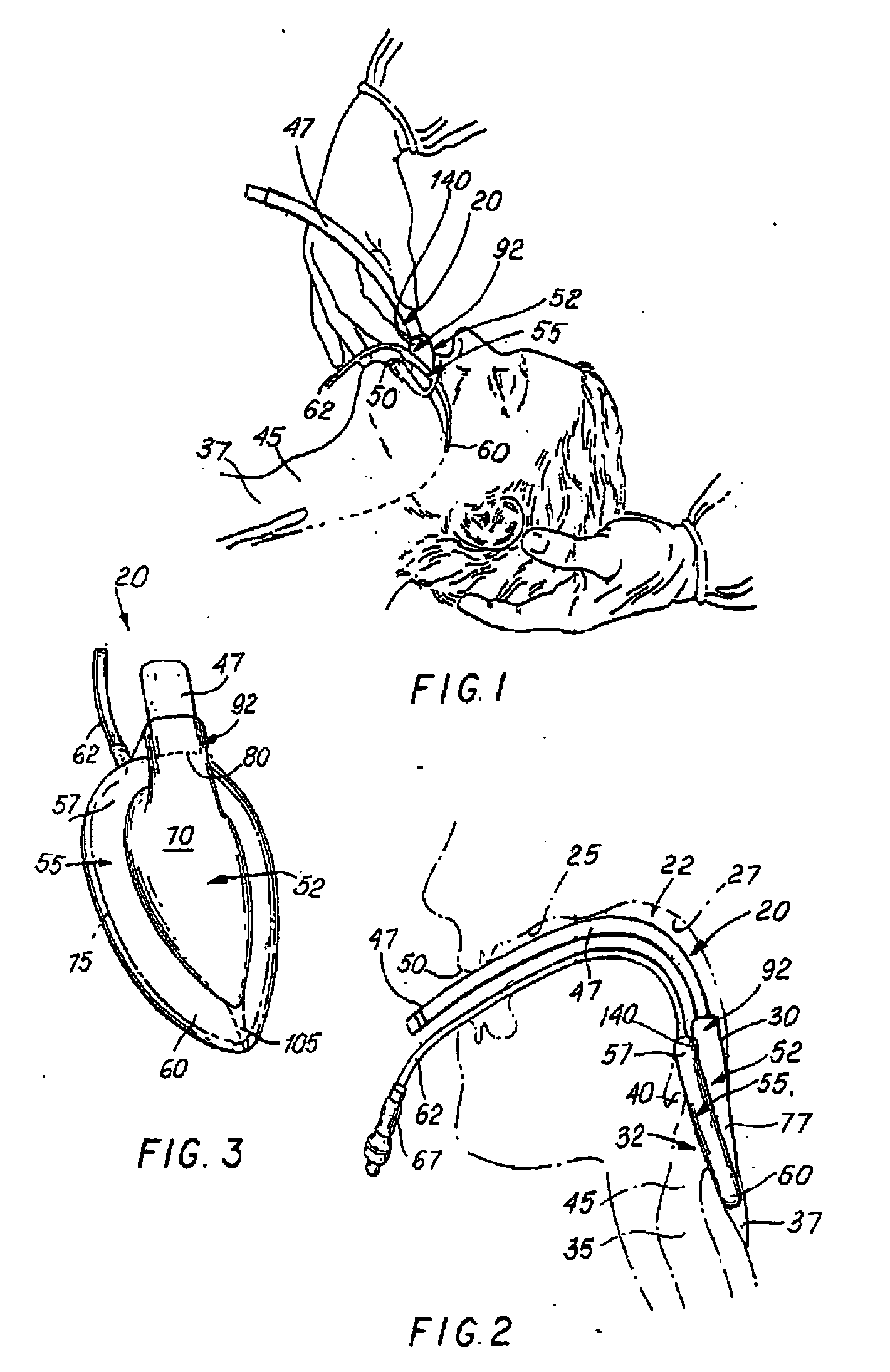
[0009] As shown in FIG. 1, insertion of the LMA-device requires use of the index finger to ensure correct placement of the LMA-device in the base of the throat. However, the index finger may slip from its intended position on the airway tube at the proximal end of the inflatable cuff, due to the presence of slippery secretions in the patient's mouth and / or the application of lubricant to assist smooth passage of the LMA-device.
[0010] In accordance with a preferred aspect of the invention, an indentation is provided on the airway tube or backplate at the intended location of finger contact to assist in locating and stabilizing the finger and to reduce the possibility of finger slippage. The indentation is situation on the surface of the airway tube adjacent its junction with the tube-joint, or on the tube-joint itself, and beneath the cuff formation surrounding the backplate. The airway tube usually has a thicker wall at this point, i.e., near the distal end of the airway tube, to form a smooth joint with the tubejoint, and the extra thickness enables the indentation to be accommodated without weakening the airway tube at this location. The tube-joint may also have a thicker wall at this point. Indeed, the indentation serves the additional useful purpose of improving the flexibility of the airway tube or tube-joint at this point. The indentation serves not only to prevent sideways slippage of the finger from the airway tube or tube-joint, but also to minimize the possibility of forward slippage and undesirable contact between the finger and the inflatable cuff, for example by the fingernail.
[0011] An additional difficulty which may occur during attempts to insert the LMA-device is that the patient's epiglottis (which protects the entrance to the glottis or larynx) may be pushed downwards or anteriorly as the LMA-device is inserted fully into the throat. Indeed, this occurs in about 40% of cases and can sometimes obstruct breathing. A conventional LMA-device has the interior of the mask which in use surrounds the glottis, communicating with the interior of the airway tube through an aperture which is traversed by two bars, known as mask aperture bars (MABs). The MABs function as a ramp up which the epiglottis slides as the mask is inserted and are intended to hold the epiglottis away from the mask floor when the LMA-device is in its correct operating location. Additionally, the MABs serve to prevent the epiglottis from obstructing the narrow entrance of the airway tube. Generally, the MABs successfully perform this function but occasionally obstruction may occur if the epiglottis is down folded, e.g., anteriorly, or if the mask is not sufficiently advanced into place.
[0012] In accordance with a preferred aspect of the invention, the aperture by which the interior of the airway tube opens into the mask is elongated and the MABs are extended to traverse the length of that aperture. By elongating the aperture to half the bowl of the mask, the range of positions of the LMA-device compatible with a clear airway is greatly increased and the angle of ramp up which the epiglottis must slide is reduced, both of which make the epiglottis less likely to be down-folded during insertion of the LMA-device.

Problems solved by technology

Additionally, the rib will substantially reduce the promontory previously formed by the distal end of the mask structure, rendering the LMA-device substantially self-inserting when it is properly deflated.

Method used


Image

  • Laryngeal mask airway device
  • Laryngeal mask airway device
  • Laryngeal mask airway device

Examples


Embodiment Construction

[0026] As used herein, the anatomical terms “anterior” and “posterior”, with respect to the human body, refer to locations nearer to the front of and to the back of the body, respectively, relative to other locations. The term “anterior-posterior (A-P)” refers to a direction, orientation or the like pointing either anteriorly or posteriorly. The anatomical terms “proximal” and “distal”, with respect to applying an instrument to the human body, refer to locations nearer to the operator and to the inside of the body, respectively. Alternatively, “distal”, as opposed to “proximal”, means further away from a given point; in this case, “distal” is used to refer to positions on the LMA-device 20 or in the body relative to the extreme outer or connector end of the LMA-device. “Proximal” is the opposite of “distal”. The term “lateral” refers to a location to the right or left sides of the body, relative to other locations. Alternatively, “lateral” means to one or other side of the mid-line,...


PUM


Abstract

A modified laryngeal mask airway device (LMA-device) is provided with means to improve ease of insertion, reliability of function and higher seal pressure (i.e., cuff pressure ratio). The LMA-device includes an indented section of the airway tube to offer locating means and purchase for the inserting finger, and extended mask aperture bars to increase the effective ventilating area of the mask and reduce the possibility of epiglottis displacement occasioned by mask insertion. The LMA-device further includes a modification of the airway tube angle of attachment to the mask, and provision of a posterior or back-cushion covering the entire posterior surface of the mask.

Description

BACKGROUND OF THE INVENTION [0001] This invention relates to laryngeal mask airway devices (LMA-devices) which are artificial airway devices permitting spontaneous or artificial ventilation of the lungs of a patient. [0002] LMA-devices are described in UK Patents Nos. 2,111,394 and 2,205,499. Such devices have become accepted items of equipment for rapidly and reliably establishing an unobstructed airway in a patient in emergency situations and in the administration of anaesthetic gases, and have found use in most countries of the world. [0003] The insertion of such a LMA-device into the throat of the patient is, in the great majority of cases an entirely straightforward procedure which can be carried out successfully following readily understandable training. FIG. 1 illustrates a preferable situation for the insertion of an LMA-device into a patient's throat. The inflatable cuff surrounding the bowl of the mask is fully deflated and correctly oriented and aligned for passage throug...

Claims


Application Information

Patent Timeline
Patent Type & Authority Applications(United States)
IPC IPC(8): A62B9/06A61M16/00A61M16/04
CPCA61M16/04A61M16/0488A61M16/0445A61M16/0409A61M2210/0656A61M16/0443
Inventor BRAIN, ARCHIBALD I. J.
Owner TELEFLEX LIFE SCI PTE LTD
Learn More